# Service Management and Orchestation
:::info
**Outline:**
[TOC]
:::
## OSC SMO Introduction

The ORAN SC (OSC) is a software community that focuses on developing and defining specifications for ORAN implementations. It is a collaborative platform for network equipment vendors, operators, and software developers to drive innovation and interoperability in the telecommunications industry [[1](https://blogs.vmware.com/telco/smo/)].
**Why Do We Need O-RAN?**
* The strong push for Future RANs to be built on a foundation of virtualized network elements, white-box hardware, and standardized interfaces.
* Create an ecosystem of multi-vendor, interoperable, autonomous, RAN that will enable rapid deployment of new & differentiated services that MNOs expect to offer in 5G.
SMO used for increasing effecienct for operational and make network maitenance cost lower. It is an effective solution for boosting operational efficiency and reducing network maintenance costs. SMO enables remote monitoring and control of functions and devices within the ORAN network, providing real-time diagnostics and troubleshooting.
The O1 Interface is a logical connection between all “O-RAN Managed Elements (MEs)” and the “management entities” within the SMO framework [[2](https://hemaprajapati.medium.com/what-is-o1-interface-in-oran-4c389cfe1bcf)]. The purpose of the O1 interface is to ensure the operation and management e.g. FCAPS, Software Management, and file management of the O-RAN components.
In other words, we can elaborate, the O1 interface enables the management of all O-RAN components that need to be orchestrated and the associated O-RAN network functions. The components managed via O1 include the near-RT RIC, the O-CU, and the O-DU in 5G NR. The O-CU corresponds to a predefined combination of O-CU-CP and O-CU-UP.

The figure above shows an extracted logical O-RAN architecture to illustrate the O1 interface and its influence on O-RAN Manage Elements, including the O-eNodeB. The O-RU termination of the O1 interface towards the SMO is currently under investigation so this interface is shown dashed.
### SMO Standards
You can read the paper here [[2](https://www.techrxiv.org/users/686134/articles/683284-unifying-3gpp-etsi-and-o-ran-smo-interfaces-enabling-slice-subnets-interoperability)]
Also the white paper [here](https://files.techmahindra.com/static/img/pdf/oran-smo-whitepaper.pdf)
### SMO Interface
The diagram below shows key interfaces in O-RAN architecture.

The SMO performs its functions/services through four key interfaces to the O-RAN Elements:
* A1 Interface between the Non-RT RIC in the SMO and the Near-RT RIC for RAN Optimization.
* O1 Interface between the SMO and the O-RAN Network Functions for FCAPS support.
* In the hybrid model, Open Fronthaul M-plane interface between SMO and O-RU for FCAPS support.
* O2 Interface between the SMO and the O-Cloud to provide platform resources and workload management.
### SMO Capabilities
The key capabilities of the SMO that provide RAN support in O-RAN are:
* FCAPS interface to O-RAN managed functions (network functions);
* Non-Real Time RIC for RAN optimization;
* O-Cloud Management, Orchestration and Workflow Management.
#### FCAPS to O-RAN Network Functions
FCAPS: Fault, Configuration, Accounting, Performance, Security. They are all the information needed for functions management. Supporting FCAPS for O1 interface:
• Performance Management (PM)
• Configuration Management (CM)
• Fault Management (FM)
• File Management
• Communications Surveillance (Heartbeat)
• Trace
• Physical Network Function (PNF) Discovery
• PNF Software Management.
#### Non-Real Time RIC for RAN optimization
SMO supports Non-RT RIC for RAN optimization.
The Non-RT RIC is comprised of two sub-functions:
* Non-RT RIC Framework – Functionality internal to the SMO Framework that logically terminates the A1 interface and exposes the required services to rApps through its R1 interface.
* Non-RT RIC Applications (rApps) – Modular applications that leverage the functionality exposed by the Non-RT RIC Framework to perform RAN optimization and other functions via the A1, O1, O2 and R1 interfaces.
#### O-Cloud Management, Orchestration and Workflow Management
The SMO utilizes the O2 interface to the O-Cloud to provide:
* The capability of managing the O-Clouds;
* Support for the orchestration of platform and application elements and workflow management.
The example functionalities should be supported in SMO:
* Discovery and administration of O-Cloud Resources
* Scale-In, Scale-Out for O-Cloud
* FCAPS (PM, CM, FM, Communication Surveillance) of O-Cloud
* Software Management of Cloud Platform
* Create, Delete Deployments and Associated Allocated O-Cloud Resources
* Scale-In, Scale-Out Deployments and Allocated O-Cloud Resources
* FCAPS (PM, FM) of Deployments and Allocated O-Cloud Resources
* Software Management of Deployments
### SMO Functions

| SMO Functions | Descriptions | Example |
|:-------------------------------------------:|:------------------------------------------------------------------------:|:-----------------------------------------------------------------------------------------------------------------------:|
| Inherent Non-RT RIC Framework Functionality | This functionality is definitively associated with the Non-RT RIC itself | The two interfaces “owned” by the Non-RT RIC: The A1 and R1 interfaces |
| Inherent O-RAN SMO Framework Functionality | This functionality is definitively not associated with the Non-RT RIC | The O1 and O2 interfaces |
| Implementation Variable Functionality | This functionality may or may not be associated with the Non-RT RIC. | An SMO provider is free to include this functionality in or exclude this functionality from a Non-RT RIC implementation |
## OSC SMO Code Structure
Here's the SMO Repository on gerrit. On the way to explore. [[3](https://gerrit.o-ran-sc.org/r/admin/repos,125)]
### SMO O1
> NONE
### SMO A1
> NONE
## OSC SMO Deployment

> This is the example of HPE Deployment [[Image 1](https://community.hpe.com/t5/image/serverpage/image-id/134800i9291C360B4F10FE6/image-size/large?v=v2&px=2000)]
### Cluster Environment
:::success
- **Hardware**
```
16 or more CPU cores
24+ GB of RAM
80 GB of Disk (mostly used to store container image)
```
- **Software**
```
Ubuntu 22.04 server
Containerd v1.7.16
Kubernetes v1.28.0 (multi node)
Calico cni v3.27.3
Release H
```
:::
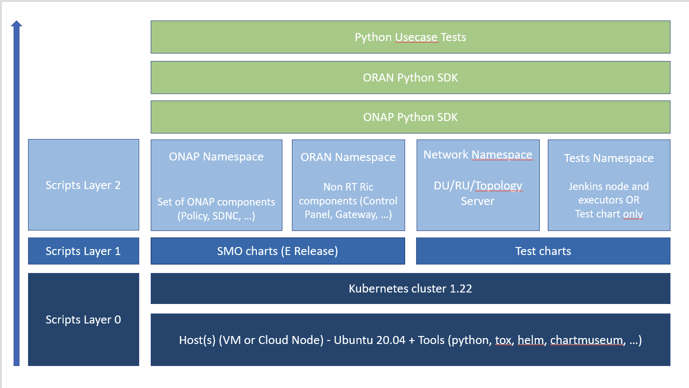
### SMO Deployment Step
1. Download the IT/dep repository from gerrit
```bash=
mkdir workspace && cd workspace
git clone --recurse-submodules https://gerrit.o-ran-sc.org/r/it/dep.git
```
:::warning
:bulb: **Note:** You need to ==add the recurse sub modules flag== as some parts are git submodules pointing to existing related charts (ONAP)
:::
2. Setup Helm Charts
- Execute the following commands being logged as root.
```bash=
##Setup ChartMuseum
./dep/smo-install/scripts/layer-0/0-setup-charts-museum.sh
```

```bash=
##Setup HELM3
./dep/smo-install/scripts/layer-0/0-setup-helm3.sh
```

```bash=
## Build ONAP/ORAN charts
./dep/smo-install/scripts/layer-1/1-build-all-charts.sh
```
3. Deploy components
- Execute the following commands ==being logged as root==:
```bash=
./dep/smo-install/scripts/layer-2/2-install-oran.sh
```
### DU / RU Simulator Step
:::warning
:bulb:**NOTE:** When all pods in "onap" and "nonrtric" namespaces are well up & running
:::
1. Modify the yaml file.
- Modify `smo-install/helm-override/default/network-simulators-override.yaml`.
- Add image tag in every simulator.
:::warning
:red_circle: **Please go to [Sonatype Nexus Repository Manager](https://nexus3.o-ran-sc.org/#browse/search=keyword%3Dnts-ng-o-ran-du) to check every simulator's version is the latest**, or you will encounter ErrImagePull issue.
:::
```shell=
ru-simulator:
image:
tag: 1.5.2
ntsimNg:
<<: *ntsimConfig
ipV6Enabled: false
sshConnections: 0
tlsConnections: 1
du-simulator:
image:
tag: 1.5.2
ntsimNg:
<<: *ntsimConfig
ipV6Enabled: false
sshConnections: 1
tlsConnections: 0
topology-server:
image:
tag: 1.8.1
ntsimNg:
<<: *ntsimConfig
ipV6Enabled: false
sshConnections: 0
tlsConnections: 1
```
2. Install Network simulator (RU / DU / Topology Server)
- Execute the following commands being logged as root:
```bash=
./dep/smo-install/scripts/layer-2/2-install-simulators.sh
```
3. Check all pods are running
```bash=
sudo kubectl get pods -n network
```

#### SDNR WEB
**Login to web console:**
- URL: https://<your host ip/>:30205/odlux/index.html
```
user: admin
password: Kp8bJ4SXszM0WXlhak3eHlcse2gAw84vaoGGmJvUy2U
```
- Result

### Monitoring Deployment Step
This step is executed after the SMO installation is complete.
1. Helm repo add and install
2.
## Contribution Plan
**Research Gap:** Look for the others SMO Feature, that SMO in OSC lack of.
### ONAP Exploration
You can easily replicate or analize the code and deployment of ONAP as the SMO here [[4](https://wiki.o-ran-sc.org/display/IAT/Automated+deployment+and+testing+-+using+SMO+package+and+ONAP+Python+SDK)]
### Juniper SMO Solutions
> Juniper has their own SMO Product for slicing ([check it](https://www.virtualexhibition.o-ran.org/classic/generation/2023/category/intelligent-ran-control-demonstrations/sub/intelligent-control/283))
### Capgemini RIC Solutions
> They have their own solution on [RIC](https://www.capgemini.com/wp-content/uploads/2023/06/RIC_brochure_Jan23-2.pdf)
### Amdocs-DELL Solutions
> Here's the blog that talked about it ([take a look](https://infohub.delltechnologies.com/en-us/p/defining-the-future-of-o-ran-management-with-vodafone-amdocs-and-dell-technologies/))
### Virtuora SMO Solutions
> Find their solutions [here](https://networkresources.global.fujitsu.com/smo-web/smo-solution-brief)
### NTT Docomo Views
> See their view on how to face vRAN [here](https://www.ntt-review.jp/archive/ntttechnical.php?contents=ntr202211fa7.pdf&mode=show_pdf)
## O-RAN Components
One of the key benefits of the Open RAN model lies in its commitment to vendor neutrality. This interoperability is maintained regardless of the specific equipment or software suppliers involved, breaking down proprietary barriers and fostering a more open, competitive ecosystem.
This is extended and enhanced by the E2 interface defined in O-RAN Alliance which together with O1 and O2 enable a standardised approach to the management, orchestration and support for real time telemetry exposure and control of the CU and DU nodes to bring AI/ML network intelligence in the RAN. [[5](https://accelleran.com/understanding-the-du-and-cu-in-open-ran-architecture/)]
This vendor neutrality gives network operators the flexibility to integrate best-in-class solutions without being tethered to one provider.
Here's the shallow definition for each components ([check it out](https://firecell.io/learn/open-ran/))
But for the detail explanation, you can check it [here](https://arxiv.org/pdf/2202.01032)
Then for the simple yet eye catching slides [here](https://lfnetworking.org/wp-content/uploads/sites/7/2022/04/SMO_slides_LFN_webinar2.pdf)
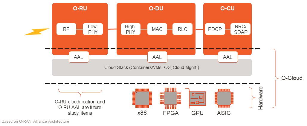
### O-CU
The Central Unit (CU) oversees the higher layers of the protocol stack, particularly the SDAP, PDCP, and RRC layers. Its primary roles encompass:
* Network Management: The CU manages broader aspects of data flow within the network, dictating how data packets journey through the infrastructure.
* Coordination with DUs: To ensure coherent communication between the core network and the Radio Units (RUs), the CU liaises with the DUs, guiding them on data management tasks.
* Strategic Decision-making: For overarching network decisions, such as user mobility management and establishing user-specific communication bearers, the CU plays a pivotal role.
To draw a parallel, the CU is akin to a symphony conductor, ensuring each section comes together harmoniously for a flawless performance.
Acronym explainers:
* SDAP (Service Data Adaptation Protocol) Layer: This layer is responsible for mapping between QoS flows and data radio bearers and for marking QoS flow ID on packets.
* PDCP (Packet Data Convergence Protocol) Layer: This layer plays a crucial role in the transmission of user data and control information between the user equipment (UE) and the network. It handles tasks such as header compression, security (ciphering and integrity protection), and in-sequence delivery of upper layer PDUs.
* RRC (Radio Resource Control) Layer: This layer is responsible for the establishment, configuration, maintenance, and release of radio bearers. It deals with aspects such as handover, broadcast of system information, paging, and control of UE measurement reporting.
### O-DU
The Distributed Unit (DU) handles the lower layers of the protocol stack, which includes the Upper Physical, MAC, and RLC layers. Its chief responsibilities are:
* Data Organisation and Management: The DU is tasked with preparing data for transmission. It structures the data, ensuring it’s in the right format for efficient radio transmission.
* Interaction with the Radio Unit (RU): The DU directly manages data communication with the Radio Unit, translating the organised data into radio waves for transmission and vice versa.
* Latency Reduction and Efficiency: Being in closer proximity to the RU and managing the lower protocol layers, the DU assures minimal latency, especially crucial for real-time data exchange applications.
Metaphorically, think of the DU as the skilled technician of a symphony, tuning the instruments to perfection before the performance.
**Acronym explainers:**
* Upper Physical Layer: This is the part of the physical layer closest to the MAC layer. It deals with aspects like modulation, encoding, and other processes essential for preparing data for transmission over the radio waves.
* MAC (Medium Access Control) Layer: This layer is responsible for how data packets are placed on the network. It addresses issues like when data may be transmitted and helps prevent collisions by managing protocol access to the physical network medium.
* RLC (Radio Link Control) Layer: This layer ensures the reliable transmission of data between the user equipment and the network. It handles segmentation, reassembly of data packets, and error correction.
### Near-RT RIC
Near-RT RIC is a logical function that enables near-real-time control and optimization of RAN elements and resources via fine-grained data collection and actions over an E2 interface.xApp, an application designed to run on the Near-RT RIC, is central to the operation of Near-RT RIC. A question that often comes up is, what does ‘x’ mean? ‘X’ stands for any, so any app designed to run on the Near-RT RIC.
Each xApp is likely to consist of one or more microservices. At the point of on-boarding, microservices will identify which data it consumes and which data it provides. The important point that has excited many within our industry is that these applications are independent of the Near-RT RIC and may be provided by any third party. The E2 interface enables a direct association between the xApp and the RAN functionality.
It is important to point out that sometimes there can be overlapping or conflicting requests from multiple xApps. This can lead to a tricky situation as each application will typically change one or more parameters with the objective of optimizing a specific metric. This is where Conflict Mitigation steps in to resolve any conflicting actions.
### Non-RT RIC
**Introduction**
The goal of Non-Real Time RAN Intelligent Controller (O-RAN Non-RT RIC) is to support intelligent RAN optimization by providing policy-based guidance, model management, and enrichment information to the Near-RT RIC function so that the RAN can be optimized. In contrary to Near-RT RIC, which sits in the RAN domain and works on a timescale of tens to hundreds of milliseconds, Non-RT RIC works within the management plane (and more particularly in Service Management and Orchestration, SMO) and operates on a timescale of seconds and minutes [[4](https://rimedolabs.com/blog/o-ran-non-rt-ric-architecture-and-rapps/)].
The functionality of the Non-RT RIC includes configuration management, device management, fault management, performance management, and lifecycle management for all network (NW) elements within O-RAN architecture. It is similar to Element Management System (EMS) and Analytics and Reporting functionalities in the traditional NWs. All RAN elements are self-configured by the Non-RT RIC, reducing the need for manual intervention. By providing timely insights into NW operations, Mobile Network Operators (MNOs) may use Non-RT RIC to better understand and optimize NW by applying pre-determined service and policy parameters. Its functionality is internal to the SMO in the O-RAN architecture and provides an A1 interface to the Near-RT RIC.
Non-RT RIC can use data analytics and Artificial Intelligence (AI)/Machine Learning (ML) training/inference to determine the RAN optimization actions for which it can leverage SMO services such as data collection and provisioning services of the O-RAN nodes. Trained models produced in the Non-RT RIC are distributed to the Near-RT RIC for runtime execution. Network slicing, security, role-based access control, and RAN sharing are example aspects that are enabled by the combined controller functions namely, Near-RT and non-RT. Standardized in [O-RAN.WG2.Non-RT-RIC-ARCH-TR-v01.00](https://specifications.o-ran.org/specifications).
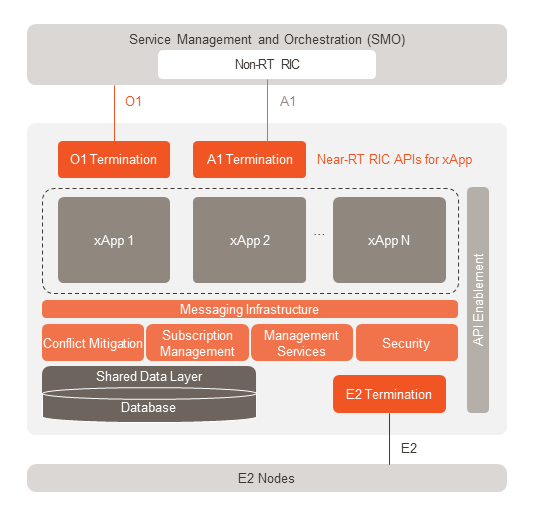
**Architecure Non-NT RIC**
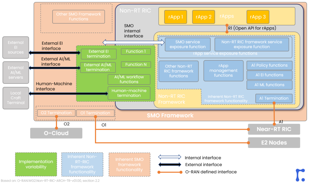
Figure above shows the internals of the SMO framework including the Non-RT RIC. Functionality inherent to the Non-RT RIC itself is colored in blue. Those functions are used basically for managing the rApps which are external to the Non-RT RIC framework accessible through an open Application Programming Interface (API), using R1 interface. Also, another set of "*blue elements*” include those that create the data to be transmitted over the A1 interface, namely: A1 policy functions, A1 enrichment information functions, A1 ML functions.
There are also parts in the SMO framework that are out of Non-RT RIC scope, marked with a *"pink-ish”* color. They are basically related to the O1/O2 termination as well as other SMO framework functions, e.g. for network slicing lifecycle management. Those are inherent to the SMO framework.
Finally, the green part refers to the functionality which implementation is flexible. Those functions could be part of Non-RT RIC and they could be also external to Non-RT RIC and sit in the SMO. They are not inherent to any of those. The example here is AI/ML workflow functions. In such light, AI/ML could be either part of Non-RT RIC, or it could be external, providing the information to the SMO service exposure functions.
### rApp Examples
rApps are applications designed to run on Non-RT RIC providing additional value-added services to help creation of policies that the Non-RT RIC framework delivers down to Near-RT RIC through the A1 interface. Fig. 2, shows Non-RT RIC with three example rApps, namely rApp R, rApp U, and rApp Q connected via R1 interface to the Non-RT RIC framework. Their inputs and outputs are as follows:
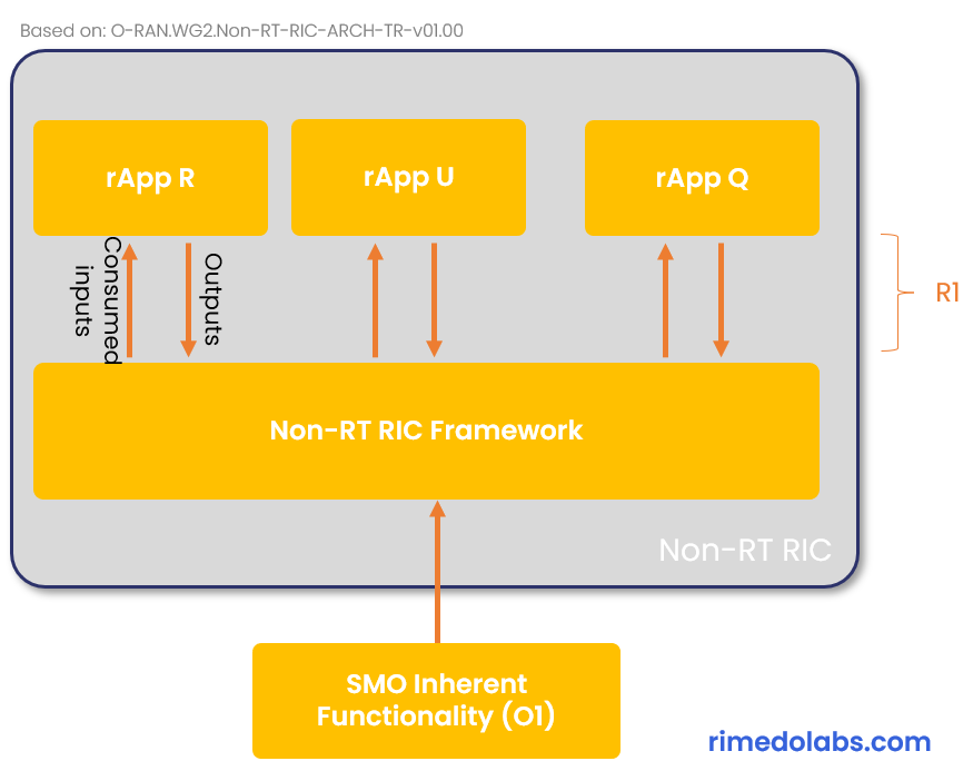
1. **rApp R**
rApp R is an rApp which consumes the O1 measurements. It takes the information from the O1 interface for RF signal experienced by a UE on serving and neighboring cells, and UE location. Based on this input, it estimates/predicts the future UE location and RF signal level when the UE moves towards a certain direction. For example, based on the past information of UEs at a given location with particular values for received signal levels from serving and neighbor base stations, and on the current measurements, it predicts the most likely UE signal levels after it moves towards predicted location.
**rApp R (RF signal predictor):**
* Consumes: O1 measurements of RF signal experienced by UE for serving/neighbor cells, measurements for UE location;
* Outputs: future time prediction of the location of UE, prediction of RF signal at that location for serving/neighbor.
2. **rApp U**
rApp U is a cell utilization predictor, which consumes the cell load utilization and amount of resources of a cell over time and outputs a future prediction of the cell load utilization, based on the trend. Doing so, it could deduct, e.g., that at the beginning of the day there is a lot of traffic in particular area, and then the traffic volume drops because all the people are moving to work so the traffic moves to the city center and thus predict the future cell load utilization.
**rApp U (Cell utilization predictor):**
* Consumes: cell utilization measurements regarding actual capacity utilization for a cell site over time;
* Outputs: future time prediction of the cell site utilization based on the trend.
3. **rApp Q**
rApp Q takes outputs from rApp R and rApp U, i.e. the predicted locations, signal levels, and cell utilization at a particular area and time, as well as the actual measurements and the actual cell utilization. Based on those it calculates the potential quality of experience (QoE). So, e.g., it could predict the future QoE if the user stays at a particular location or in different future location, for a scenario, where UE stays at the same cell or is handed over to another one.
**rApp Q (UE QoE predictor):**
* Consumes: measurements of UE RF signal (actual RAN measurement or prediction), measurement of cell site capacity utilization (actual or prediction)
* Calculates: QoE experienced by particular UE, e.g.:
* Estimates actual QoE based on actual RF signal and actual cell utilization.
* Estimates QoE if in a neighbor cell based on actual RF signal relative to neighbor cell and actual neighbor cell utilization.
* Estimates future QoE if connected to serving/neighbor cell-based predicted signal and predicted cell utilization.
## O-RAN Use Cases
### O-RAN in AWS
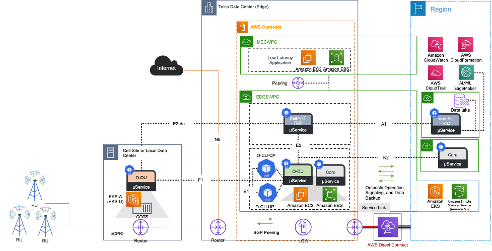
> You can review it [here](https://docs.aws.amazon.com/whitepapers/latest/open-radio-access-network-architecture-on-aws/o-ran-architecture-on-aws.html)
### SMO in NTN
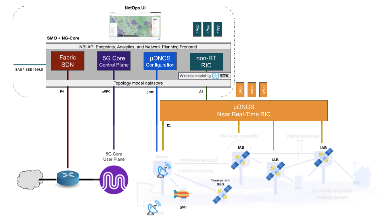
> You can review the paper [here](https://ieeexplore.ieee.org/stamp/stamp.jsp?arnumber=9843390)
### HLD OSC Lab
> You can see more HLD [here](https://arxiv.org/pdf/2208.14885)
### SMO Use Cases By Rakuten