# How to Build a Flight Controller using a Microcontroller
*By Julio Nyakunga (Open Skies Fellow)*
In this post I will demonstrate how to build a flight controller using an Atmega328p Microcontroller.
### Why am I doing this
Before we begin this lets see why we need to learn how to build a flight controller. This might sound weird to some people but for enthusiasts in technology it is good news. Below are the reasons for building a flight controller
* It helps you to have a low level understanding on how drones work.
* It can help you understand how to perform drone maintenance.
* Making your own flight controller gives you full access to its feature so you can modify its setting whenever you want.
* It is a good use of available electronics devices that are cheaper and easy to get.
### Steps on how to make a flight controller
1. Circuit designing
2. Circuit printing and assembling
3. Coding and circuit programming
4. Flight controller PID tuning and testing
I will go through each step for you to understand what it means and what needs to be done.
### 1. Circuit Designing
Before on start designing the circuit must figure out what are the circuit rewquirements: what functions it is going to perform
1. How many inputs and what type of inputs it will receive?
2. How many outputs and what type of outputs it will produce? and
3. What kind of processing will be needed?
Having the answers for these questions will help one choose the right electronic devices for the circuit, for example one should know the number of inputs and outputs needed so the he/she can select a microcontroller of a given number of input and putput digital and analog pins.
Below is the list of input and output signals in my flight controller:
| Signal name | Signal Type | Direction |
| -------- | -------- | -------- |
| Throttle | PPM analog | input |
| Rudder | PPM analog | input |
| Elevator | PPM analog | input |
| Aileron | PPM analog | input |
| ESC 1 | PWM analog | output |
| ESC 2 | PWM analog | output |
| ESC 3 | PWM analog | output |
| ESC 4 | PWM analog | output |
| I2C Clock | digital | output |
| I2C Data | digital | input/output |
From the table we can see that 8 digital pins are needed for PPM PWM signal generations and 2 analog piins are needed for I2C communications.
At this point, I know which microcontroller and electronic devices will be used to make the flight controller.
Below is the list of electronic devices I used to make my flight controller circuit.
1. Atmega328P Microcontroller
3. 16Mhz Crystal Oscillator
4. 2 22p Ceramic Capacitor
5. 1 Push Button Switch
6. 1 10K Resistor
7. 3 200/220 Resistor
8. 3 LED Diode
9. 1x8 Female Pin header
10. 2x4 Female Pin header
11. 1x4 Female Pin header
12. Microcontroller chip Holder
13. MPU-9265 (Gyroscope, Accelerometer and Magnetometer)
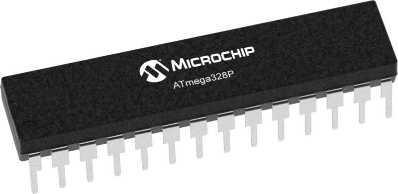
##### The Atmega328P Microcontroller
ATmega328P Microcontroller is a general purpose microcontroller with 14 digital pins and 6 analogy pins. This is a programmable integrated circuit (IC), which one can use to perform and automate different tasks. I used this microcontroller to make the flight controller circuit.
The Microcontroller circuit will be connected to some peripheral electronic components with which it can effectively control the drone. The microcontroller will receive control signals from RF Transmitter through RF Receiver, and decode the signals, will also read and process gyroscope and accelerometer data for drone balancing. Finally the Microcontroller will control the speed of motors using electronic speed controllers (ESC) using PWM (Pulse Width Modulation) signals.
##### What is IMU?
IMU stands for Inertial Measurement Unit, it is a collection of a number of sensors (measurement tools) and their embedded software that process sensor raw data. IMU is installed in a device (drone) and is used to capture device's movements. IMUs contain sensors such as accelerometer, gyroscope, and magnetometer.
##### How does an IMU work?
IMU can measure a variety of factors including speed, directions, acceleration, angular rate, and magnetic field surrounding the device (drone).
Each sensor/toot in an IMU is used to measure different factors about the device (drone):
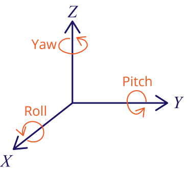
##### The Gyroscope
The gyroscope is part of IMU used to measure angular acceleration and velocity. Gyroscope can measure angular acceleration on the X, Y and Z axis. Using its raw output data angular acceleration and angular displacement can be calculated. Using the gyroscope, the roll, pitch and yaw angle of the drone can be measured. The gyroscope is very accurate but has its shortcomings, one being the gyro drifting due to its high sensitivity to mechanical vibrations. Gyro drifting is the tendency of the gyro angle to drift from it's true value when there are mechanical vibrations in the system.
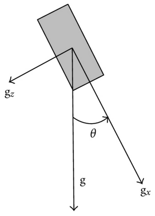
##### The Accelerometer
Accelerometer is part of IMU used to measure linear acceleration and velocity. Accelerometer can measure linear acceleration along X, Y and Z directions. Using its raw output data, linear acceleration and so orientation of the drone can be determined. The accelerometer is less accurate for short time angular measurement but very reliable for long time measurement and not highly affected by mechanical vibrations (noises) as gyroscope. But the shortcoming of an accelerometer is you can not use it to measure yaw angle.
##### The Magnetometer
The magnetometer is part of IMU used to measure magnetic field surrounding a device and so can be used to establish directional heading of a the device (drone). I used Magnetometer in my flight controller circuit to fix the head of the drone in one direction.
Each of these sensors have their strengths and weaknesses, for example gyroscope it very accurate for short time angular measurement but very vulnerable to mechanical shock and high frequency vibrations (leading to gyro drifting), while accelerometer is not accurate for short time angular measurement but its advantage is it is not vulnerable to mechanical shock and high frequency vibrations (noises), also accelerometer can not be used to measure yaw angle. In short I can say output from an individual sensor in the IMU system is by itself not reliable and not useful unless other sensors' outputs are used.
Due to these advantages and disadvantages of IMU sensors, the IMU system rationally combines outputs from different sensors (mentined above) to produce an accurate and reliable output. This technique is called sensor fusion.
So I did a fusion of gyroscope angle and accelerometer angle to get an accurate roll and pitch angle.
NOTE
> In my flight controller circuit the I used MPU-9265 to implement the IMU hardware system. MPU-9265 is a multi-chip module (MCM) consisting of two dies integrated into a single Quad Flat No-lead (QFN) package. One die houses the 3-Axis gyroscope and the 3-Axis accelerometer. The other die houses the AK8963 3-Axis magnetometer. So I all the gyroscope, accelerometer and magnetometer in one chip.
##### Schematic Circuit Diagram
I used Proteus Software to make this schematic circuit diagram. You can use any software of your choice to make your schematic circuit diagram.
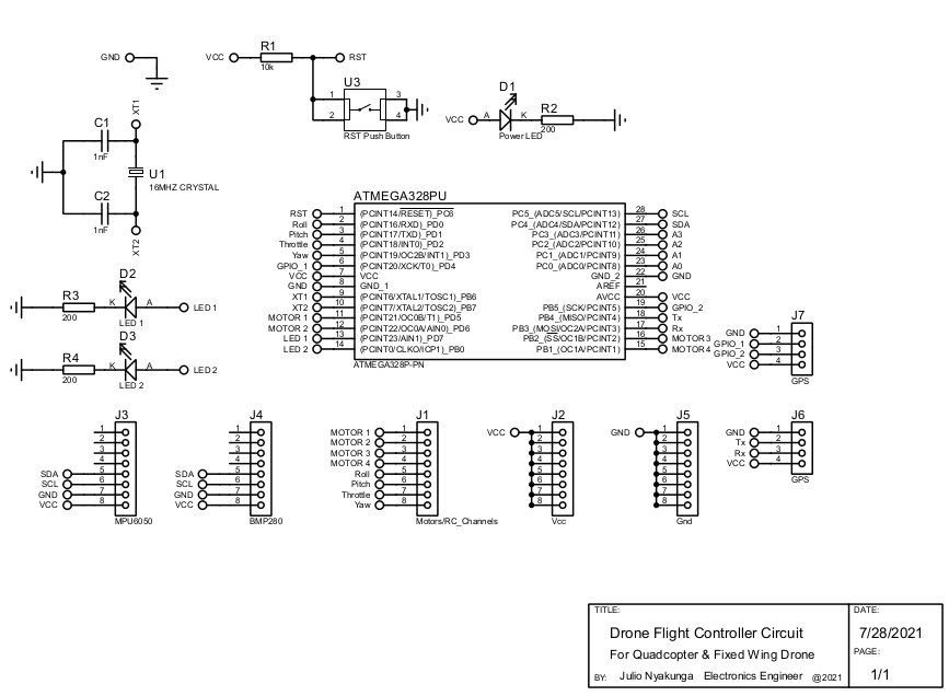
NOTE
> Not all electronic devices need to be included in your schematic circuit diagram, some need to just connect to the circuit using jumper wires and pin headers, so only pin headers are included in the diagram.
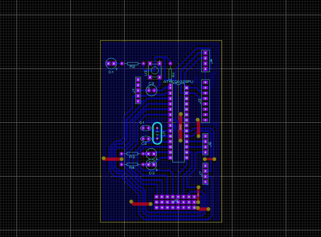
##### PCB Designing
Using Proteus Software I made the PCB design of the circuit. Below is the picture of my PCB design
### 2. Circuit Printing and Assembling
After finishing my design I had to order a printing service from <a href="https://bafredo.com/">Bafredo Electronics</a> in Dar es Salaam, where I printed and assembled my circuit board. PCB assembling is all about soldering work with respect to the design diagram made.
#### PCB, before assembling
.jpeg)
.jpeg)
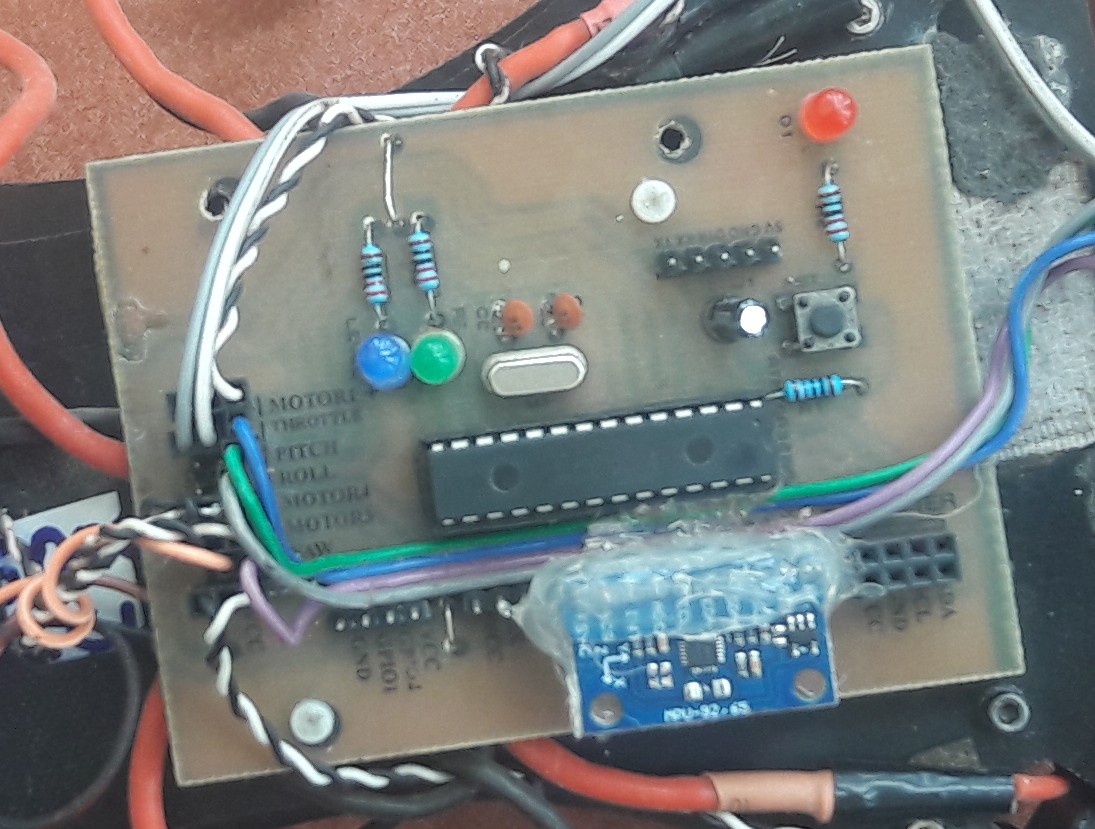
#### PCB, after assembling
.jpeg)
.jpeg)
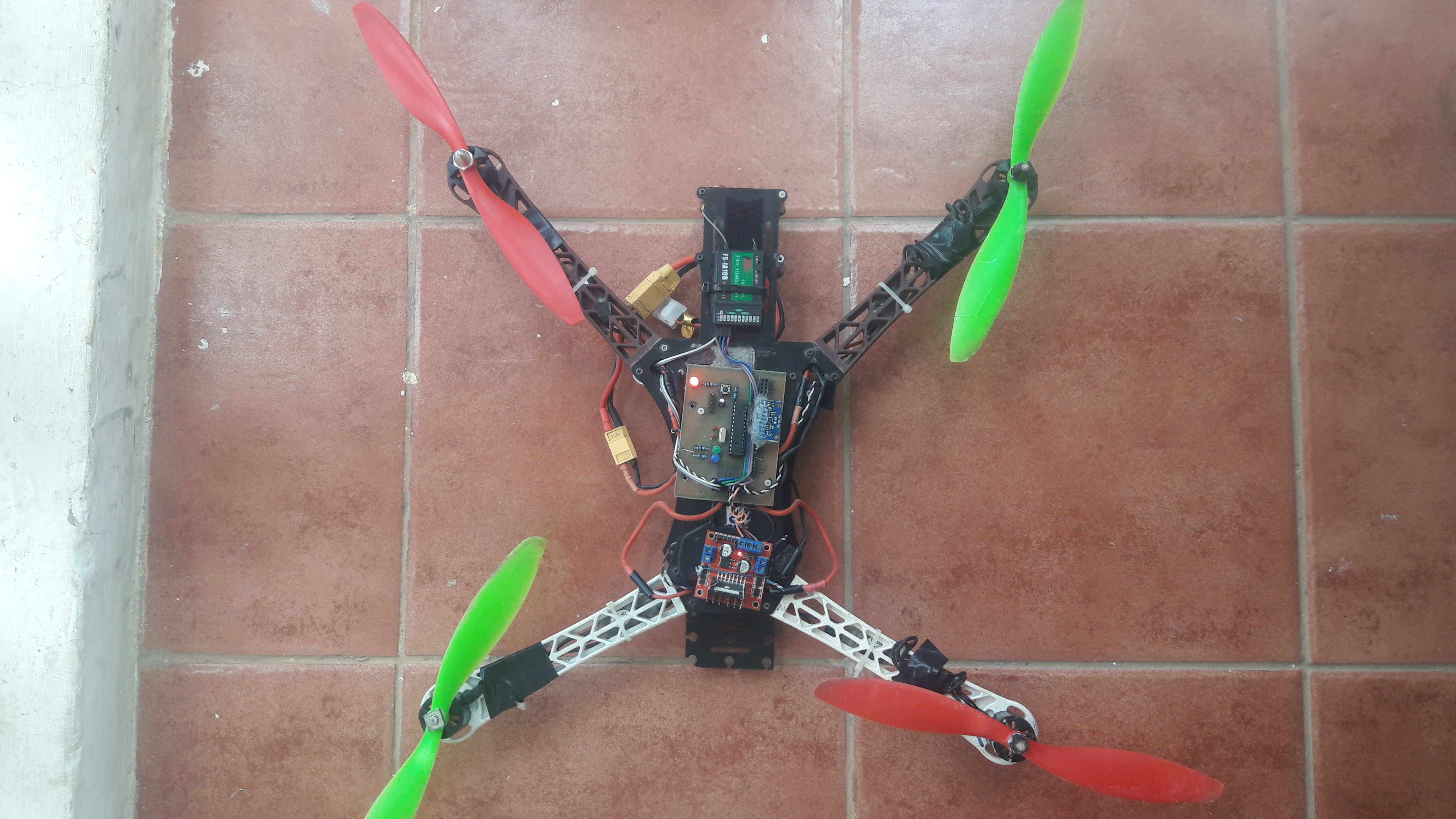
#### The Flight Controller Circuit (mounted on the DJI F450 Frame)
### 3. Coding and Circuit Programming
After I was done with hardware work I had to sit for programming. I wrote the program (sketch) for the flight controller using Arduino Software (IDE) using a C and C++ based language.
I used Arduino IDE to program the Circuit. ```Arduino Code``` for the circuit is in the folder named Quadcopter_Flight_Controller in my Github Repository, [View Code](https://github.com/giulionyakunga/Quad-Flight-Controller/blob/main/Quadcopter_Flight_Controller/Quadcopter_Flight_Controller.ino)
### 4. Flight Controller PID Tuning and Testing
Before testing the flight controller I had to tune PID values for the drone. PID stands for Proportional Derivative and Integral, in drone control system we normally use a PID controller which is a piece of embedded systems code that controls drone responsiveness to change in its angular orientations. So PID tuning is the process of finding constant values for this piece of code. The constant values are required for both roll, pitch and yaw angle control and each of these angle controls need an individual value for its proportional, derivative and integral terms. PID tuning is a trial-and-error process but it is funny once you understand what is PID Controller, what does each term in the controller mean, what is the effect of change each term in the controller and once you understand what your doing. Here are some links to read more about PID Controllers <a href="https://www.technik-consulting.eu/en/optimizing/drone_PID-optimizing.html">Link_1</a>, <a href="https://visaya.solutions/de/article/pid-controller-small-quad-copter-drones">Link_2</a> and <a href="https://oscarliang.com/quadcopter-pid-explained-tuning/">Link_3</a>
After hard work of PID tuning I went on testing my flight controller
{%youtube afa5Onz6GLc %}
Click <a href="https://youtu.be/afa5Onz6GLc">here</a> to view my YouTube video when I was testing the flight controller.
#### The Drone
### Challenges
Throughout the implementation of this project I have faced lots of challenges. The major challenge is instability of the drone.
### Conclusion
The instability of the drone is mainly caused by existance of mechanical vibrations and poor tuned PID controller. So the instability of the drone can be improved by improving my IMU code (IMU software implementation), improving drone vibration damping system and well tuning the PDI constants. Improved IMU code will help to come out with a system that can filter out mechanical vibrations produced by spinning motors and propellers. Also PID tuning will also help providing better results.
**Thank You for Reading
**
<iframe src="https://docs.google.com/forms/d/e/1FAIpQLSf1_AhFcTi6SYMriSi_kF4F_8MxMUFwIOkK8R9t2RS27lpSdg/viewform?embedded=true" width="640" height="408" frameborder="0" marginheight="0" marginwidth="0">Loading…</iframe>
---
### Open Skies Fellows
This project was fully supported by Open Skies Fellows (OSF). Open Skies Fellows is a fellowship program led by OpenMap Development Tanzania, Uhurulabs and the Humanitarian OpenStreetMap Team, with aim to support youth and give them a chance and responsibility to gain social-technological skills to leverage their potential to solve community challenges using frontier technologies.
<p align="center">
<img width="460" height="300" src="https://i.imgur.com/Uea2Uas.png">
<p align="center">
Open Skies Fellow
"We Design, We Build and We Fly"</p>
</p>
---
### About Me

Name: Julio Nyakunga
Graduate Engineer, Telecommunications Engineering
College of Information and Communication Technologies
University of Dar es Salaam, 2019
Email: giulionyakunga@gmail.com
Mobile Phone: +255672120941, +255766032160
Physical address: Kijitonyama, Dar es Salaa, Tanzania
---


