* # ARM 指令
###### tags: `armtech`
## ARM 與 MIPS

* [ARM Processor Architecture](https://developer.arm.com/architectures/learn-the-architecture/introducing-the-arm-architecture), ARM Ltd.
* [MIPS Processor](https://en.wikipedia.org/wiki/MIPS_architecture)
* 智慧財產和經營權多次易主: 2012 年併購 MIPS、2017 年 Imagination 出售 MIPS 智慧財產權,2018 年 6 月美國矽谷新創 AI 晶片公司 Wave Computing 宣布完成收購 MIPS 公司股權,MIPS 公司維持獨立運作,隔年 5 月 Wave Computing 聲請破產保護,MIPS 公司運作不受影響。
## ARM Processor Architecture

ARMv8 中文翻譯可見此:[http://wiki.csie.ncku.edu.tw/embedded/ARMv8](http://wiki.csie.ncku.edu.tw/embedded/ARMv8)
**A64** is a new 32-bit fixed length instruction set to support the AArch64 execution state. The following is a summary of the A64 ISA features.
* Clean decode table based on 5-bit register specifiers
* Instruction semantics broadly the same as in AArch32
* 31 general purpose 64-bit registers accessible at all times
* No modal banking of GP registers - Improved performance and energy
* Program counter (PC) and Stack pointer (SP) not general purpose registers
* Dedicated zero register available for most instructions
ARM, generically known as **A32**, is a fixed-length (32-bit) instruction set. It is the base 32-bit ISA used in the ARMv4T, ARMv5TEJ and ARMv6 architectures. In these architectures it is used in applications requiring high performance, or for handling hardware exceptions such as interrupts and processor start-up.
The ARM ISA is also supported in the [Cortex™-A](http://www.arm.com/products/processors/cortex-a/index.php) and [Cortex-R](http://www.arm.com/products/processors/cortex-r/index.php) profiles of the Cortex architecture for performance critical applications, and for legacy code. Most of its functionality is subsumed into the Thumb instruction set with the introduction of Thumb-2 technology. Thumb (**T32**) benefits from improved code density.
ARM instructions are 32-bits wide, and are aligned on 4-byte boundaries.
Most ARM instructions can be "conditionalized" to only execute when previous instructions have set a particular condition code. This means that instructions only have their normal effect on the programmers’ model operation, memory and coprocessors if the N, Z, C and V flags in the Application Program Status Register satisfy a condition specified in the instruction. If the flags do not satisfy this condition, the instruction acts as a NOP, that is, execution advances to the next instruction as normal, including any relevant checks for exceptions being taken, but has no other effect. This conditionalization of instructions allows small sections of if- and while-statements to be encoded without the use of branch instructions.
==>
**A64**’s Key differences from A32 are:
* New instructions to support 64-bit operands. Most instructions can have 32-bit or 64-bit arguments
* Addresses assumed to be 64-bits in size. LP64 and LLP64 are the primary data models targeted
* Far fewer conditional instructions than in AArch32 conditional {branches, compares, selects}
* No arbitrary length load/store multiple instructions LD/ST ‘P’ for handling pairs of registers added A64
==> [64-bit data model](https://en.wikipedia.org/wiki/64-bit_computing#64-bit_data_models)
## ARM Architecture
ARM 是在全球中被廣泛使用的 processor cores,像是 PDA、手機、多媒體播放器、數位電視、相機等等。ARM processors 有許多 family,如 ARM7、 ARM9、 ARM11、ARMv7,同一個 family 的設計使用相似的設計原則及同一個common instruction set。他的設計哲學是用有限的硬體( 有限的 memory 和 physical size restrictions) 資源達到 high code density。
**ARM 的命名方式 (Cortex系列以前) - ARMxyzTDMIEJFS**
(在 ARM Cortex-A/R/M之前的 "ARM Classic")
* x: 處理器系列
* y: 記憶體管理單元 (MMU)
* z: cache
* T: 支援 Thumb 指令集
* D: 支援 debugger
* M: 支援快速乘法 ( Multiplier )
* I: 支援 [Embedded ICE](https://en.wikipedia.org/wiki/In-circuit_emulation) (built-in debugger hardware)
* E: 支援增強型 DSP 指令 (Enhanced instruction)
* J: 支援 [Jazelle ](https://en.wikipedia.org/wiki/Jazelle)(JVM)
* F: 具備向量浮點單元 VFP ( Floating-point)
* -S: Synthesizible version (source code version for EDA tools)
ps : TDMI 這四項基本功能成了任何新產品的標準配備,於是就不再使用這4個後綴。但是新的後綴不斷加入,包括定義存儲器界面的,定義高速快取的,以及定義"緊耦合存儲器(TCM)"的,於是形成了新一套命名法,這套命名法一直使用至今。比如ARM1176JZF-S,它實際上預設就支持TDMI功能,除此之外還支持JZF。
這套命名機制在 ARM Cortex-A/R/M 之後,徹底棄置。以 MMU 來說,ARM Cortex-A 系列都有 MMU,而 Cortex-M0/M0+/M3/M4 均缺乏 MMU,僅有選擇性的 MPU。[Cortex-M7](http://www.arm.com/products/processors/cortex-m/cortex-m7-processor.php) 開始提供 **cache 和 TCM**
**ARM Classic**
(在 ARM Cortex 系列出現之前)
* ARM7TDMI (armv4)
* 3 級 pipeline (fetch/decode/execute)
* 高密度程式/低功耗
* One of the most used ARM-version (for low-end systems)
* 在 ARM7TDMI 之後版本的所有 ARM cores 都具備 TDMI
* ARM9TDMI (armv4)
* 與 ARM7
* 5 stages (fetch/decode/execute/memory/write)
* Separate instruction and data cache
* ARM11
* ARMv6 架構,是Cortex-A的基礎
**ARM 採用 RISC**
ARM architecture 從 Berkeley RISC design合併了幾個特點,但也有些並無採用。
<div style="color: rgb(0, 0, 0); font-family: Helvetica; font-size: medium; letter-spacing: normal;">* Features used</div>
* a load-store architecture
* 固定長度 32-bit instructions
* 3-address instruction 形式
<div style="color: rgb(0, 0, 0); font-family: Helvetica; font-size: medium; letter-spacing: normal;">* Features rejected</div>
* register window
* 主要原因在於 register window是一塊由許多暫存器所佔據的、很大的chip 空間
* delayed branches
* 主要原因在於 delayed branches remove the atomicity of individual instructions.在super-scalar 和 branch prediction mechanisms 無法好好相互配合
* single-cycle execution of all instructions
* 還是有些指令需要超過2個或2個以上的cycle執行
**ARM 的架構**

註: MAC = [Multiply–accumulate operation](https://en.wikipedia.org/wiki/Multiply%E2%80%93accumulate_operation)

**ARM Register**
以下是ARM的 register,在User/System Mode時,可以使用r0~r15,其中r13為stack pointer,r14為link register,r15為program counter

Current Program Status Register(CPSR) : 在user-level時,用於存取condition code bits

溢位複習:
* 1、輸入的數是[無符號整數](https://zh.wikipedia.org/w/index.php?title=%E6%97%A0%E7%AC%A6%E5%8F%B7%E6%95%B4%E6%95%B0&action=edit&redlink=1),我們通過觀察C判斷是否溢出
a) C=1
i)如果是加法操作,結果不正確,結果溢出
ii)如果是減法操作,結果正確,結果未溢出
b) C=0
i)如果是加法操作,結果正確,結果未溢出
ii)如果是減法操作,結果不正確,結果未溢出。在這種情況下,結果是負數。然而,在無符號整數世界裡,負數不存在,我們認識這樣的操作是非法的。當然,如果認為答案是以有符號整數[補碼](https://zh.wikipedia.org/wiki/%E8%A1%A5%E7%A0%81)的形式出現,則結果正確。
* 2、輸入的數是[有符號整數](https://zh.wikipedia.org/w/index.php?title=%E6%9C%89%E7%AC%A6%E5%8F%B7%E6%95%B4%E6%95%B0&action=edit&redlink=1),我們通過觀察V判斷是否溢出
a) V=1,結果不正確,結果溢出
b) V=0,結果正確,結果未溢出
通用暫存器有6種 data types ( signed / unsigned) ( word /Half word/ byte),而在所有ARM的運算為32-bit,比較小的資料型態只有在資料傳送的運算中被支援。
Program Counter ( PC ) 是儲存要被執行的位址,而所有指令皆為 32-bit wide 且 word aligned
在 ARM 架構中支援了 ( 7+1 )種模式,如圖:

**Instruction sets**
裡面有 ARM / Thumb / Jazelle ,下圖為簡單介紹:
(實際上 ARM 的 extension 遠比以下列出的多)

**Pipeline**
在執行時, PC 是 8 bytes ahead,也就是說 Pipeline 準備要做 Execute級( 位址是 0x8000)時,要讀取的下一個位置是 PC + 8 的位置(從範例中可清楚看見,即 DCD 指令的位址 0x8008)

他有以下幾點特點:
* 當 Pipeline 在做 branch 或者直接修改 PC 值的話, 會造成 ARM core flush 他的 pipeline
* ARM10 開始使用 branch prediction
* 即使發生中斷,也會將 Pipeline 中所有指令執行完才會去做中斷的事情
**Interrupts**
當發生 exception 或 interrupt 時,會觸發 Interrupt handler,此時,他會尋找 vector table 去做中斷時所要處理的 routine.

下圖為中斷定義及其跳躍的起始位址:

* 筆記 2 - [ARM Instructions](http://www.csie.ntu.edu.tw/~cyy/courses/assembly/12fall/lectures/handouts/lec09_ARMisa.pdf)
在 user-mode program 中,可以看到 15 個 32-bit general purpose registers (R0-R14), program counter (PC) 及 CPSR,在指令集中有定義一些指令可以改變 state。
在開始深入探討前,先來看看他的 Memory system吧~
**Memory system**
* memory 是一個 linear array of **bytes addressed**,範圍從 0 ~ 2^32^ -1
* 有 word, half-word, byte 三種形式
* 採取 Little Endian

剛剛有提到 Little Endian,他其實是 Byte ordering 的其中一種方式,endian指的是當物理上的最小單元比邏輯上的最小單元還要更小時,邏輯單元對映到物理單元的排佈關係。舉例來說:
如果你在文件上看到一個雙字組的data,Ex: `long MyData=0x12345678`,要寫到從0x0000開始的記憶體位址時。
1. 如果是Big Endian的系統: (TCP/IP)
* 存到記憶體會變成 0x12 0x34 0x56 0x78,最高位元組在位址最低位元,最低位元組在位址最高位元,依次排列。
1. 如果是Little Endian的系統:
* 存到記憶體會變成 0x78 0x56 0x34 0x12,最低位元組在最低位元,最高位元組在最高位元,反序排列。
比較的結果就是這樣:
<table style="color: rgb(0, 0, 0); font-family: Helvetica; letter-spacing: normal; font-size: 13px;">
<tbody>
<tr>
<td class="added" style="border: 1px solid rgb(153, 153, 153); min-width: 50px; height: 22px; line-height: 16px; padding-right: 4px; padding-left: 4px;"></td>
<td class="added" style="border: 1px solid rgb(153, 153, 153); min-width: 50px; height: 22px; line-height: 16px; padding-right: 4px; padding-left: 4px;">big-endian</td>
<td class="added" style="border: 1px solid rgb(153, 153, 153); min-width: 50px; height: 22px; line-height: 16px; padding-right: 4px; padding-left: 4px;">little-endian</td>
</tr>
<tr>
<td class="added" style="border: 1px solid rgb(153, 153, 153); min-width: 50px; height: 22px; line-height: 16px; padding-right: 4px; padding-left: 4px;">0x0000</td>
<td class="added" style="border: 1px solid rgb(153, 153, 153); min-width: 50px; height: 22px; line-height: 16px; padding-right: 4px; padding-left: 4px;">0x12</td>
<td class="added" style="border: 1px solid rgb(153, 153, 153); min-width: 50px; height: 22px; line-height: 16px; padding-right: 4px; padding-left: 4px;">0x78</td>
</tr>
<tr>
<td class="added" style="border: 1px solid rgb(153, 153, 153); min-width: 50px; height: 22px; line-height: 16px; padding-right: 4px; padding-left: 4px;">0x0001</td>
<td class="added" style="border: 1px solid rgb(153, 153, 153); min-width: 50px; height: 22px; line-height: 16px; padding-right: 4px; padding-left: 4px;">0x34</td>
<td class="added" style="border: 1px solid rgb(153, 153, 153); min-width: 50px; height: 22px; line-height: 16px; padding-right: 4px; padding-left: 4px;">0x56</td>
</tr>
<tr>
<td class="added" style="border: 1px solid rgb(153, 153, 153); min-width: 50px; height: 22px; line-height: 16px; padding-right: 4px; padding-left: 4px;">0x0002</td>
<td class="added" style="border: 1px solid rgb(153, 153, 153); min-width: 50px; height: 22px; line-height: 16px; padding-right: 4px; padding-left: 4px;">0x56</td>
<td class="added" style="border: 1px solid rgb(153, 153, 153); min-width: 50px; height: 22px; line-height: 16px; padding-right: 4px; padding-left: 4px;">0x34</td>
</tr>
<tr>
<td class="added" style="border: 1px solid rgb(153, 153, 153); min-width: 50px; height: 22px; line-height: 16px; padding-right: 4px; padding-left: 4px;">0x0003</td>
<td class="added" style="border: 1px solid rgb(153, 153, 153); min-width: 50px; height: 22px; line-height: 16px; padding-right: 4px; padding-left: 4px;">0x78</td>
<td class="added" style="border: 1px solid rgb(153, 153, 153); min-width: 50px; height: 22px; line-height: 16px; padding-right: 4px; padding-left: 4px;">0x12</td>
</tr>
</tbody>
</table>
**Features of ARM instruction set**
* Load-store architecture
* 3-address instructions
* 每個指令都可以做 Conditional execution
* 可以一次 load / store 多個暫存器
* 指令可以結合 shift 和 ALU operations (像是 add, sub)
**Instruction set**
可分成三大項:
* Data processing
* move
* arithmetic
* logical
* comparison
* multiply
* Data movement (memory access)
* Flow control
**Data processing**
資料處理指令包含對資料做 移動、算數、邏輯、比較、乘法 的指令,且大部分的 data processing instructions 可以對一個 operand 做 shift,如圖:

* Arithmetic operations:
* ADD : simple addition
* ADC : add with carry
* SUB : subtract
* SBC : subtract with carry
* RSB : reverse subtraction
* RSC : reverse subtraction with carry
* 示範:
```
ADD r0, r1, r2 ; r0 := r1 + r2
ADC r0, r1, r2 ; r0 := r1 + r2 + C
SUB r0, r1, r2 ; r0 := r1 - r2
SBC r0, r1, r2 ; r0 := r1 - r2 + C - 1
RSB r0, r1, r2 ; r0 := r2 - r1
RSC r0, r1, r2 ; r0 := r2 - r1 + C - 1
```
* Bit-wise logical operations:
* BIC : bit clear
* 示範
```
AND r0, r1, r2 ; r0 := r1 and r2
ORR r0, r1, r2 ; r0 := r1 or r2
EOR r0, r1, r2 ; r0 := r1 xor r2
BIC r0, r1, r2 ; r0 := r1 and not r2
```
* Register movement operations:
* MOV r0, r2 ; r0 := r2
* MVN r0, r2 ; r0 := not r2
* Comparison operations:
只設定在CPSR的 condition code bits(N, Z, C and V)
* CMP : compare
* CMN : compare negated
* TST : (bit) test
* TEQ : test equal
* 示範
```
CMP r1, r2 ; set CC on r1 - r2
CMN r1, r2 ; set CC on r1 + r2
TST r1, r2 ; set CC on r1 and r2
TEQ r1, r2 ; set CC on r1 xor r2
```
> 這裡的CC代表CPSR的 condition code bits
* Immediate operands:
* 示範
```
ADD r3, r3, #1 ; r3 := r3 + 1
AND r8, r7, #&ff ; r8 := r7[7:0]
```
* 一般在 `#` 後放置數字,則表示十進位數值; 而在 `#` 後放置 `&` 符號,可表示十六進位數值
* 若載入 32-bit 常數,該怎麼作?如果要在 r0 暫存器中,存放 0xDEADBEEF ([Hexspeak](https://en.wikipedia.org/wiki/Hexspeak) ),最直接想到這樣作
```
mov r0, 0xDEADBEEF
```
* 以編碼的角度來說,這是不可能的!為何?ARMv7 (含) 之前,所有的指令都是 32 bit (opcode + operand),以 mov 來說,所有的 32 bit 自然包含 mov 指令本身、目標 register,以及目標值。因此,不可能將任意的 32-bit 編碼的值存放到 32 bit 指令中
* MIPS 的作法: [Loading a 32 bit Immediate](https://courses.cs.washington.edu/courses/cse378/01au/files/pdf/378-ln8.pdf)
* 直接表示值對 ARM 來說,實際是一個 8-bit 數值和一個旋轉因子,所以可表達 32-bit 直接數值,但 0x1FF 不是 8-bit 數值,而 0xF000F000 也不可,因為無法經由旋轉而變成 8-bit 數值
* 所以我們得這樣作
```
load_32bit:
ldr r0, [pc #0] ;請注意: pc 位於目前位址向前 8 bytes 的地方
bx lr
.word 0xDEADBEEF
```
* 由於已經知道資料的位址,可透過 ldr 指令告訴 ARM 去取數值並且載入到暫存器。在 ARM pipeline,PC 總是位於相對於目前指令再提前兩道指令的位址
* 在 ARMv7 後,引入兩個步驟的指令來載入數值: movw, movt
```
movw r0, #0xbeef ; r0 = 0x0000beef
movt r0, #0xdead ; r0 = deadbeef
```
* GNU as 給予便利的寫法
```
.equ label, 0xDEADBEEF
movw r0, #:lower16:label
movt r0, #:upper16:label
```
* Reference: [https://sourceware.org/ml/binutils/2014-02/msg00157.html](https://sourceware.org/ml/binutils/2014-02/msg00157.html)
**Shifted register operands:**
舉例來說:
* ADD r3, r2, r1, LSL #3 ; r3 := r2 + ( r1 << 3 )
* LSL : logical shift left by 0 to 31 places; fill the vacated bits at the least significant end of the word with zeros
* LSR : lgoical shift right by 0 to 32 places; fill the vacated bits at the most significant end of the word with zeros
* ASL : arithmetic shift left; this is a synonym for LSL
* ASR : arithmetic shift right by 0 to 32 places; Register contents are treated as two’s complement signed integers.; fill the vacated bits at the most significant end of the word with the sign bit
* ROR : rotate right. Provides the value of the contents of a register rotated by a value. The bits that are rotated off the right end are inserted into the vacated bit positions on the left.
* RRX : provides the value of the contents of a register shifted right one bit. The old carry flag is shifted into bit[31]. If the S suffix is present, the old bit[0] is placed in the carry flag.

位移 (shift) 主要分兩種:
* [](https://en.wikipedia.org/wiki/Logical_shift)[https://en.wikipedia.org/wiki/Logical_shift](https://en.wikipedia.org/wiki/Logical_shift) (邏輯移位)
* [](https://en.wikipedia.org/wiki/Arithmetic_shift)[https://en.wikipedia.org/wiki/Arithmetic_shift](https://en.wikipedia.org/wiki/Arithmetic_shift) (算數移位)
簡單來說,邏輯移位無論左移右移,一律都是把多出來的位數填零。算術運算左移跟邏輯移位一樣填零,右移需要考慮到 singed 的屬性,假若最高位是 1,則填補1,反之若最高位是 0,則填補0。
範例:
* signed int a = 1234;
* signed int b = 6;
* signed int r = a >> b ; / * 邏輯平移運算 */
* unsigned int a = 1234 ;
* int b = 6 ;
* unsigned int r = a >> 6 ; /* 算數平移運算 */
注意: ARM Toolchain (包含 arm-none-eabi/linux-gnueabi) 預設將 "int" 視為 "unsigned"
* mov r0, [#8000000F](https://embedded2016.hackpad.com/ep/search/?q=%238000000F&via=qJ1HvbwU4ns)
* 將數值 `0x8000000F` 放入暫存器 r0 中
* <r0> | 1 0 0 0 | 0 0 0 0 | 0 0 0 0 | 0 0 0 0 | 0 0 0 0 | 0 0 0 0 | 0 0 0 0 | 1 1 1 1 |
* mov r1, r0, LSL #1
* r0 左移 1 bit 後,將值放入 r1 中
* <r1> | 0 0 0 0 | 0 0 0 0 | 0 0 0 0 | 0 0 0 0 | 0 0 0 0 | 0 0 0 0 | 0 0 0 1 | 1 1 1 0 |
* 向左位移後,讀取 r0 的值,經過 barrier shifter 後,數值變成 0x1E
* bit 31 向左位移後,超過 32 bit 範圍,會被捨棄,而 bit 4, 3, 2, 1 分別位移到 bit 5, 4, 3, 2
* `mov r1, r0, lsl #2` 等價於 `r1 = (int) (r0 << 2)`
* barrier shift
<div style="color: rgb(0, 0, 0); font-family: Helvetica; font-size: medium; letter-spacing: normal;">* Condition flags</div>
If S is specified, these instructions update the condition code bits
* Logical or move operation 不更新 C or V, shift operation (除RRX外)不更新 C
Ex:
* ADDS r2, r2, r0 ; 32-bit carry out -> C ..
<div style="color: rgb(0, 0, 0); font-family: Helvetica; font-size: medium; letter-spacing: normal;">* Multiplies:</div>
* MUL r4, r3, r2 ; r4 := (r3 * r2)[31:0]
<div style="color: rgb(0, 0, 0); font-family: Helvetica; font-size: medium; letter-spacing: normal;">* Encoding data processing instructions</div>
這裡可以看第 25-bit(#) 決定 operand 2 是以何種格式,如果 # = 1 就如圖下只有 1 種對應格式,如果 # = 0就需要再比對位置在第四個bit ( 決定2種格式 )

**Flow Control**
決定哪一條指令將被執行
* B{<cond>} label
* BL{<cond>} label
* BX{<cond>} Rm
* BLX{<cond>} label | Rm
<table style="color: rgb(0, 0, 0); font-family: Helvetica; letter-spacing: normal; font-size: 13px;">
<tbody>
<tr>
<td class="added" style="border: 1px solid rgb(153, 153, 153); min-width: 50px; height: 22px; line-height: 16px; padding-right: 4px; padding-left: 4px;">B</td>
<td class="added" style="border: 1px solid rgb(153, 153, 153); min-width: 50px; height: 22px; line-height: 16px; padding-right: 4px; padding-left: 4px;">branch</td>
<td class="added" style="border: 1px solid rgb(153, 153, 153); min-width: 50px; height: 22px; line-height: 16px; padding-right: 4px; padding-left: 4px;">pc = label pc-relative offset within 32MB</td>
</tr>
<tr>
<td class="added" style="border: 1px solid rgb(153, 153, 153); min-width: 50px; height: 22px; line-height: 16px; padding-right: 4px; padding-left: 4px;">BL</td>
<td class="added" style="border: 1px solid rgb(153, 153, 153); min-width: 50px; height: 22px; line-height: 16px; padding-right: 4px; padding-left: 4px;">branch with link</td>
<td class="added" style="border: 1px solid rgb(153, 153, 153); min-width: 50px; height: 22px; line-height: 16px; padding-right: 4px; padding-left: 4px;">pc = label</td>
</tr>
<tr>
<td class="added" style="border: 1px solid rgb(153, 153, 153); min-width: 50px; height: 22px; line-height: 16px; padding-right: 4px; padding-left: 4px;">BX</td>
<td class="added" style="border: 1px solid rgb(153, 153, 153); min-width: 50px; height: 22px; line-height: 16px; padding-right: 4px; padding-left: 4px;">branch exchange</td>
<td class="added" style="border: 1px solid rgb(153, 153, 153); min-width: 50px; height: 22px; line-height: 16px; padding-right: 4px; padding-left: 4px;">pc = Rm & 0xfffffffe, T = Rm & 1</td>
</tr>
<tr>
<td class="added" style="border: 1px solid rgb(153, 153, 153); min-width: 50px; height: 22px; line-height: 16px; padding-right: 4px; padding-left: 4px;">BLX</td>
<td class="added" style="border: 1px solid rgb(153, 153, 153); min-width: 50px; height: 22px; line-height: 16px; padding-right: 4px; padding-left: 4px;">branch exchange with link</td>
<td class="added" style="border: 1px solid rgb(153, 153, 153); min-width: 50px; height: 22px; line-height: 16px; padding-right: 4px; padding-left: 4px;">pc = label, T = 1</td>
</tr>
</tbody>
</table>
<table style="color: rgb(0, 0, 0); font-family: Helvetica; letter-spacing: normal; font-size: 13px;">
<tbody>
<tr>
<td class="added" style="border: 1px solid rgb(153, 153, 153); min-width: 50px; height: 22px; line-height: 16px; padding-right: 4px; padding-left: 4px;">Mnemonic</td>
<td class="added" style="border: 1px solid rgb(153, 153, 153); min-width: 50px; height: 22px; line-height: 16px; padding-right: 4px; padding-left: 4px;">Name</td>
<td class="added" style="border: 1px solid rgb(153, 153, 153); min-width: 50px; height: 22px; line-height: 16px; padding-right: 4px; padding-left: 4px;">Condition flags</td>
</tr>
<tr>
<td class="added" style="border: 1px solid rgb(153, 153, 153); min-width: 50px; height: 22px; line-height: 16px; padding-right: 4px; padding-left: 4px;">EQ</td>
<td class="added" style="border: 1px solid rgb(153, 153, 153); min-width: 50px; height: 22px; line-height: 16px; padding-right: 4px; padding-left: 4px;">equal</td>
<td class="added" style="border: 1px solid rgb(153, 153, 153); min-width: 50px; height: 22px; line-height: 16px; padding-right: 4px; padding-left: 4px;">Z</td>
</tr>
<tr>
<td class="added" style="border: 1px solid rgb(153, 153, 153); min-width: 50px; height: 22px; line-height: 16px; padding-right: 4px; padding-left: 4px;">NE</td>
<td class="added" style="border: 1px solid rgb(153, 153, 153); min-width: 50px; height: 22px; line-height: 16px; padding-right: 4px; padding-left: 4px;">not equal</td>
<td class="added" style="border: 1px solid rgb(153, 153, 153); min-width: 50px; height: 22px; line-height: 16px; padding-right: 4px; padding-left: 4px;">z</td>
</tr>
<tr>
<td class="added" style="border: 1px solid rgb(153, 153, 153); min-width: 50px; height: 22px; line-height: 16px; padding-right: 4px; padding-left: 4px;">CS HS</td>
<td class="added" style="border: 1px solid rgb(153, 153, 153); min-width: 50px; height: 22px; line-height: 16px; padding-right: 4px; padding-left: 4px;">carry set/unsigned higher or the same</td>
<td class="added" style="border: 1px solid rgb(153, 153, 153); min-width: 50px; height: 22px; line-height: 16px; padding-right: 4px; padding-left: 4px;">C</td>
</tr>
<tr>
<td class="added" style="border: 1px solid rgb(153, 153, 153); min-width: 50px; height: 22px; line-height: 16px; padding-right: 4px; padding-left: 4px;">CC LO</td>
<td class="added" style="border: 1px solid rgb(153, 153, 153); min-width: 50px; height: 22px; line-height: 16px; padding-right: 4px; padding-left: 4px;">carry clear/unsigned lower</td>
<td class="added" style="border: 1px solid rgb(153, 153, 153); min-width: 50px; height: 22px; line-height: 16px; padding-right: 4px; padding-left: 4px;">c</td>
</tr>
<tr>
<td class="added" style="border: 1px solid rgb(153, 153, 153); min-width: 50px; height: 22px; line-height: 16px; padding-right: 4px; padding-left: 4px;">MI</td>
<td class="added" style="border: 1px solid rgb(153, 153, 153); min-width: 50px; height: 22px; line-height: 16px; padding-right: 4px; padding-left: 4px;">minus/negative</td>
<td class="added" style="border: 1px solid rgb(153, 153, 153); min-width: 50px; height: 22px; line-height: 16px; padding-right: 4px; padding-left: 4px;">N</td>
</tr>
<tr>
<td class="added" style="border: 1px solid rgb(153, 153, 153); min-width: 50px; height: 22px; line-height: 16px; padding-right: 4px; padding-left: 4px;">PL</td>
<td class="added" style="border: 1px solid rgb(153, 153, 153); min-width: 50px; height: 22px; line-height: 16px; padding-right: 4px; padding-left: 4px;">plus/positive or zero</td>
<td class="added" style="border: 1px solid rgb(153, 153, 153); min-width: 50px; height: 22px; line-height: 16px; padding-right: 4px; padding-left: 4px;">n</td>
</tr>
<tr>
<td class="added" style="border: 1px solid rgb(153, 153, 153); min-width: 50px; height: 22px; line-height: 16px; padding-right: 4px; padding-left: 4px;">VS</td>
<td class="added" style="border: 1px solid rgb(153, 153, 153); min-width: 50px; height: 22px; line-height: 16px; padding-right: 4px; padding-left: 4px;">overflow</td>
<td class="added" style="border: 1px solid rgb(153, 153, 153); min-width: 50px; height: 22px; line-height: 16px; padding-right: 4px; padding-left: 4px;">V</td>
</tr>
<tr>
<td class="added" style="border: 1px solid rgb(153, 153, 153); min-width: 50px; height: 22px; line-height: 16px; padding-right: 4px; padding-left: 4px;">VC</td>
<td class="added" style="border: 1px solid rgb(153, 153, 153); min-width: 50px; height: 22px; line-height: 16px; padding-right: 4px; padding-left: 4px;">no overflow</td>
<td class="added" style="border: 1px solid rgb(153, 153, 153); min-width: 50px; height: 22px; line-height: 16px; padding-right: 4px; padding-left: 4px;">v</td>
</tr>
<tr>
<td class="added" style="border: 1px solid rgb(153, 153, 153); min-width: 50px; height: 22px; line-height: 16px; padding-right: 4px; padding-left: 4px;">HI</td>
<td class="added" style="border: 1px solid rgb(153, 153, 153); min-width: 50px; height: 22px; line-height: 16px; padding-right: 4px; padding-left: 4px;">unsigned higer</td>
<td class="added" style="border: 1px solid rgb(153, 153, 153); min-width: 50px; height: 22px; line-height: 16px; padding-right: 4px; padding-left: 4px;">zC</td>
</tr>
<tr>
<td class="added" style="border: 1px solid rgb(153, 153, 153); min-width: 50px; height: 22px; line-height: 16px; padding-right: 4px; padding-left: 4px;">LS</td>
<td class="added" style="border: 1px solid rgb(153, 153, 153); min-width: 50px; height: 22px; line-height: 16px; padding-right: 4px; padding-left: 4px;">unsigned lower or same</td>
<td class="added" style="border: 1px solid rgb(153, 153, 153); min-width: 50px; height: 22px; line-height: 16px; padding-right: 4px; padding-left: 4px;">Z or c</td>
</tr>
<tr>
<td class="added" style="border: 1px solid rgb(153, 153, 153); min-width: 50px; height: 22px; line-height: 16px; padding-right: 4px; padding-left: 4px;">GE</td>
<td class="added" style="border: 1px solid rgb(153, 153, 153); min-width: 50px; height: 22px; line-height: 16px; padding-right: 4px; padding-left: 4px;">signed greater than or equal</td>
<td class="added" style="border: 1px solid rgb(153, 153, 153); min-width: 50px; height: 22px; line-height: 16px; padding-right: 4px; padding-left: 4px;">NV or nv</td>
</tr>
<tr>
<td class="added" style="border: 1px solid rgb(153, 153, 153); min-width: 50px; height: 22px; line-height: 16px; padding-right: 4px; padding-left: 4px;">LT</td>
<td class="added" style="border: 1px solid rgb(153, 153, 153); min-width: 50px; height: 22px; line-height: 16px; padding-right: 4px; padding-left: 4px;">signed less than</td>
<td class="added" style="border: 1px solid rgb(153, 153, 153); min-width: 50px; height: 22px; line-height: 16px; padding-right: 4px; padding-left: 4px;">Nv or nV</td>
</tr>
<tr>
<td class="added" style="border: 1px solid rgb(153, 153, 153); min-width: 50px; height: 22px; line-height: 16px; padding-right: 4px; padding-left: 4px;">GT</td>
<td class="added" style="border: 1px solid rgb(153, 153, 153); min-width: 50px; height: 22px; line-height: 16px; padding-right: 4px; padding-left: 4px;">signed greater than</td>
<td class="added" style="border: 1px solid rgb(153, 153, 153); min-width: 50px; height: 22px; line-height: 16px; padding-right: 4px; padding-left: 4px;">NzV or nzv</td>
</tr>
<tr>
<td class="added" style="border: 1px solid rgb(153, 153, 153); min-width: 50px; height: 22px; line-height: 16px; padding-right: 4px; padding-left: 4px;">LE</td>
<td class="added" style="border: 1px solid rgb(153, 153, 153); min-width: 50px; height: 22px; line-height: 16px; padding-right: 4px; padding-left: 4px;">signed less than or equal</td>
<td class="added" style="border: 1px solid rgb(153, 153, 153); min-width: 50px; height: 22px; line-height: 16px; padding-right: 4px; padding-left: 4px;">Z or Nv or nV</td>
</tr>
<tr>
<td class="added" style="border: 1px solid rgb(153, 153, 153); min-width: 50px; height: 22px; line-height: 16px; padding-right: 4px; padding-left: 4px;">AL</td>
<td class="added" style="border: 1px solid rgb(153, 153, 153); min-width: 50px; height: 22px; line-height: 16px; padding-right: 4px; padding-left: 4px;">always (unconditional)</td>
<td class="added" style="border: 1px solid rgb(153, 153, 153); min-width: 50px; height: 22px; line-height: 16px; padding-right: 4px; padding-left: 4px;">ingnored</td>
</tr>
</tbody>
</table>
<table style="color: rgb(0, 0, 0); font-family: Helvetica; letter-spacing: normal; font-size: 13px;">
<tbody>
<tr>
<td class="added" style="border: 1px solid rgb(153, 153, 153); min-width: 50px; height: 22px; line-height: 16px; padding-right: 4px; padding-left: 4px;">Branch</td>
<td class="added" style="border: 1px solid rgb(153, 153, 153); min-width: 50px; height: 22px; line-height: 16px; padding-right: 4px; padding-left: 4px;">Interpretation</td>
<td class="added" style="border: 1px solid rgb(153, 153, 153); min-width: 50px; height: 22px; line-height: 16px; padding-right: 4px; padding-left: 4px;">Normal uses</td>
</tr>
<tr>
<td class="added" style="border: 1px solid rgb(153, 153, 153); min-width: 50px; height: 22px; line-height: 16px; padding-right: 4px; padding-left: 4px;">B BAL</td>
<td class="added" style="border: 1px solid rgb(153, 153, 153); min-width: 50px; height: 22px; line-height: 16px; padding-right: 4px; padding-left: 4px;">Unconditional</td>
<td class="added" style="border: 1px solid rgb(153, 153, 153); min-width: 50px; height: 22px; line-height: 16px; padding-right: 4px; padding-left: 4px;">Always take this branch</td>
</tr>
<tr>
<td class="added" style="border: 1px solid rgb(153, 153, 153); min-width: 50px; height: 22px; line-height: 16px; padding-right: 4px; padding-left: 4px;">BEQ</td>
<td class="added" style="border: 1px solid rgb(153, 153, 153); min-width: 50px; height: 22px; line-height: 16px; padding-right: 4px; padding-left: 4px;">Equal</td>
<td class="added" style="border: 1px solid rgb(153, 153, 153); min-width: 50px; height: 22px; line-height: 16px; padding-right: 4px; padding-left: 4px;">Comparison equal or zero result</td>
</tr>
<tr>
<td class="added" style="border: 1px solid rgb(153, 153, 153); min-width: 50px; height: 22px; line-height: 16px; padding-right: 4px; padding-left: 4px;">BNE</td>
<td class="added" style="border: 1px solid rgb(153, 153, 153); min-width: 50px; height: 22px; line-height: 16px; padding-right: 4px; padding-left: 4px;">Not equal</td>
<td class="added" style="border: 1px solid rgb(153, 153, 153); min-width: 50px; height: 22px; line-height: 16px; padding-right: 4px; padding-left: 4px;">Comparison not eaual or non-zero result</td>
</tr>
<tr>
<td class="added" style="border: 1px solid rgb(153, 153, 153); min-width: 50px; height: 22px; line-height: 16px; padding-right: 4px; padding-left: 4px;">BPL</td>
<td class="added" style="border: 1px solid rgb(153, 153, 153); min-width: 50px; height: 22px; line-height: 16px; padding-right: 4px; padding-left: 4px;">Plus</td>
<td class="added" style="border: 1px solid rgb(153, 153, 153); min-width: 50px; height: 22px; line-height: 16px; padding-right: 4px; padding-left: 4px;">Result positive or zero</td>
</tr>
<tr>
<td class="added" style="border: 1px solid rgb(153, 153, 153); min-width: 50px; height: 22px; line-height: 16px; padding-right: 4px; padding-left: 4px;">BMI</td>
<td class="added" style="border: 1px solid rgb(153, 153, 153); min-width: 50px; height: 22px; line-height: 16px; padding-right: 4px; padding-left: 4px;">Minus</td>
<td class="added" style="border: 1px solid rgb(153, 153, 153); min-width: 50px; height: 22px; line-height: 16px; padding-right: 4px; padding-left: 4px;">Result minus or zero</td>
</tr>
<tr>
<td class="added" style="border: 1px solid rgb(153, 153, 153); min-width: 50px; height: 22px; line-height: 16px; padding-right: 4px; padding-left: 4px;">BLO</td>
<td class="added" style="border: 1px solid rgb(153, 153, 153); min-width: 50px; height: 22px; line-height: 16px; padding-right: 4px; padding-left: 4px;">Lower</td>
<td class="added" style="border: 1px solid rgb(153, 153, 153); min-width: 50px; height: 22px; line-height: 16px; padding-right: 4px; padding-left: 4px;">Unsigned comparison gave lower</td>
</tr>
<tr>
<td class="added" style="border: 1px solid rgb(153, 153, 153); min-width: 50px; height: 22px; line-height: 16px; padding-right: 4px; padding-left: 4px;">BHS</td>
<td class="added" style="border: 1px solid rgb(153, 153, 153); min-width: 50px; height: 22px; line-height: 16px; padding-right: 4px; padding-left: 4px;">or the same</td>
<td class="added" style="border: 1px solid rgb(153, 153, 153); min-width: 50px; height: 22px; line-height: 16px; padding-right: 4px; padding-left: 4px;">Unsigned comparison gave higher or same</td>
</tr>
<tr>
<td class="added" style="border: 1px solid rgb(153, 153, 153); min-width: 50px; height: 22px; line-height: 16px; padding-right: 4px; padding-left: 4px;">BVC</td>
<td class="added" style="border: 1px solid rgb(153, 153, 153); min-width: 50px; height: 22px; line-height: 16px; padding-right: 4px; padding-left: 4px;">Overflow clear</td>
<td class="added" style="border: 1px solid rgb(153, 153, 153); min-width: 50px; height: 22px; line-height: 16px; padding-right: 4px; padding-left: 4px;">Signed integer operation; no overflow occured</td>
</tr>
<tr>
<td class="added" style="border: 1px solid rgb(153, 153, 153); min-width: 50px; height: 22px; line-height: 16px; padding-right: 4px; padding-left: 4px;">BVS</td>
<td class="added" style="border: 1px solid rgb(153, 153, 153); min-width: 50px; height: 22px; line-height: 16px; padding-right: 4px; padding-left: 4px;">Overflow set</td>
<td class="added" style="border: 1px solid rgb(153, 153, 153); min-width: 50px; height: 22px; line-height: 16px; padding-right: 4px; padding-left: 4px;">Signed integer operation; overflow occured</td>
</tr>
<tr>
<td class="added" style="border: 1px solid rgb(153, 153, 153); min-width: 50px; height: 22px; line-height: 16px; padding-right: 4px; padding-left: 4px;">BGT</td>
<td class="added" style="border: 1px solid rgb(153, 153, 153); min-width: 50px; height: 22px; line-height: 16px; padding-right: 4px; padding-left: 4px;">Greater than</td>
<td class="added" style="border: 1px solid rgb(153, 153, 153); min-width: 50px; height: 22px; line-height: 16px; padding-right: 4px; padding-left: 4px;">Signed integer comparison gave greater than</td>
</tr>
<tr>
<td class="added" style="border: 1px solid rgb(153, 153, 153); min-width: 50px; height: 22px; line-height: 16px; padding-right: 4px; padding-left: 4px;">BGE</td>
<td class="added" style="border: 1px solid rgb(153, 153, 153); min-width: 50px; height: 22px; line-height: 16px; padding-right: 4px; padding-left: 4px;">Greater than or equal</td>
<td class="added" style="border: 1px solid rgb(153, 153, 153); min-width: 50px; height: 22px; line-height: 16px; padding-right: 4px; padding-left: 4px;">Signed integer comparison gave greater than or equal</td>
</tr>
<tr>
<td class="added" style="border: 1px solid rgb(153, 153, 153); min-width: 50px; height: 22px; line-height: 16px; padding-right: 4px; padding-left: 4px;">BLT</td>
<td class="added" style="border: 1px solid rgb(153, 153, 153); min-width: 50px; height: 22px; line-height: 16px; padding-right: 4px; padding-left: 4px;">Less than</td>
<td class="added" style="border: 1px solid rgb(153, 153, 153); min-width: 50px; height: 22px; line-height: 16px; padding-right: 4px; padding-left: 4px;">Signed integer comparison gave less than</td>
</tr>
<tr>
<td class="added" style="border: 1px solid rgb(153, 153, 153); min-width: 50px; height: 22px; line-height: 16px; padding-right: 4px; padding-left: 4px;">BLE</td>
<td class="added" style="border: 1px solid rgb(153, 153, 153); min-width: 50px; height: 22px; line-height: 16px; padding-right: 4px; padding-left: 4px;">Less or equal</td>
<td class="added" style="border: 1px solid rgb(153, 153, 153); min-width: 50px; height: 22px; line-height: 16px; padding-right: 4px; padding-left: 4px;">Signed integer comparison gave less than or equal</td>
</tr>
<tr>
<td class="added" style="border: 1px solid rgb(153, 153, 153); min-width: 50px; height: 22px; line-height: 16px; padding-right: 4px; padding-left: 4px;">BHI</td>
<td class="added" style="border: 1px solid rgb(153, 153, 153); min-width: 50px; height: 22px; line-height: 16px; padding-right: 4px; padding-left: 4px;">Higher</td>
<td class="added" style="border: 1px solid rgb(153, 153, 153); min-width: 50px; height: 22px; line-height: 16px; padding-right: 4px; padding-left: 4px;">Unsigned comparison gave higher</td>
</tr>
<tr>
<td class="added" style="border: 1px solid rgb(153, 153, 153); min-width: 50px; height: 22px; line-height: 16px; padding-right: 4px; padding-left: 4px;">BLS</td>
<td class="added" style="border: 1px solid rgb(153, 153, 153); min-width: 50px; height: 22px; line-height: 16px; padding-right: 4px; padding-left: 4px;">Lower or the same</td>
<td class="added" style="border: 1px solid rgb(153, 153, 153); min-width: 50px; height: 22px; line-height: 16px; padding-right: 4px; padding-left: 4px;">Unsigned comparison gave lower or same</td>
</tr>
</tbody>
</table>
**Data transfer instructions**
> (許願: 希望能有餐廳結帳和超商為何有提款機的故事的文字版)
data processing 的 mov 指令是暫存器間互相傳送資料,而 data transfer instructions 是暫存器與 memory 間互相傳遞資料,而 data transfer instructions 有三種基本形式
1. Single register load/store ,也就是對單一暫存器做 load/store
2. Multiple register load/store,可以對多個暫存器做 load/store
3. Single register swap: SWP(B), atomic instruction for semaphore
<h2 style="color: rgb(0, 0, 0); font-family: Helvetica; font-size: medium; letter-spacing: normal;">* Syntax:</h2>
* <LDR|STR>{<cond>} {B} Rd, addressing1
* LDR{<cond>}SB|H|SH Rd, addressing2
* STR{<cond>}H Rd, addressing2
2
<table style="color: rgb(0, 0, 0); font-family: Helvetica; letter-spacing: normal; font-size: 13px;">
<tbody>
<tr>
<td class="added" style="border: 1px solid rgb(153, 153, 153); min-width: 50px; height: 22px; line-height: 16px; padding-right: 4px; padding-left: 4px;">LDR</td>
<td class="added" style="border: 1px solid rgb(153, 153, 153); min-width: 50px; height: 22px; line-height: 16px; padding-right: 4px; padding-left: 4px;">load word into a register</td>
<td class="added" style="border: 1px solid rgb(153, 153, 153); min-width: 50px; height: 22px; line-height: 16px; padding-right: 4px; padding-left: 4px;">Rd <-- mem32[address]</td>
</tr>
<tr>
<td class="added" style="border: 1px solid rgb(153, 153, 153); min-width: 50px; height: 22px; line-height: 16px; padding-right: 4px; padding-left: 4px;">STR</td>
<td class="added" style="border: 1px solid rgb(153, 153, 153); min-width: 50px; height: 22px; line-height: 16px; padding-right: 4px; padding-left: 4px;">save byte or word from a register</td>
<td class="added" style="border: 1px solid rgb(153, 153, 153); min-width: 50px; height: 22px; line-height: 16px; padding-right: 4px; padding-left: 4px;">Rd --> mem32[address]</td>
</tr>
<tr>
<td class="added" style="border: 1px solid rgb(153, 153, 153); min-width: 50px; height: 22px; line-height: 16px; padding-right: 4px; padding-left: 4px;">LDRB</td>
<td class="added" style="border: 1px solid rgb(153, 153, 153); min-width: 50px; height: 22px; line-height: 16px; padding-right: 4px; padding-left: 4px;">load byte into a register</td>
<td class="added" style="border: 1px solid rgb(153, 153, 153); min-width: 50px; height: 22px; line-height: 16px; padding-right: 4px; padding-left: 4px;">Rd <-- mem8[address]</td>
</tr>
<tr>
<td class="added" style="border: 1px solid rgb(153, 153, 153); min-width: 50px; height: 22px; line-height: 16px; padding-right: 4px; padding-left: 4px;">STRB</td>
<td class="added" style="border: 1px solid rgb(153, 153, 153); min-width: 50px; height: 22px; line-height: 16px; padding-right: 4px; padding-left: 4px;">save byte from a register</td>
<td class="added" style="border: 1px solid rgb(153, 153, 153); min-width: 50px; height: 22px; line-height: 16px; padding-right: 4px; padding-left: 4px;">Rd --> mem8[address]</td>
</tr>
<tr>
<td class="added" style="border: 1px solid rgb(153, 153, 153); min-width: 50px; height: 22px; line-height: 16px; padding-right: 4px; padding-left: 4px;">LDRH</td>
<td class="added" style="border: 1px solid rgb(153, 153, 153); min-width: 50px; height: 22px; line-height: 16px; padding-right: 4px; padding-left: 4px;">load halfword into a register</td>
<td class="added" style="border: 1px solid rgb(153, 153, 153); min-width: 50px; height: 22px; line-height: 16px; padding-right: 4px; padding-left: 4px;">Rd <-- mem16[address]</td>
</tr>
<tr>
<td class="added" style="border: 1px solid rgb(153, 153, 153); min-width: 50px; height: 22px; line-height: 16px; padding-right: 4px; padding-left: 4px;">STRH</td>
<td class="added" style="border: 1px solid rgb(153, 153, 153); min-width: 50px; height: 22px; line-height: 16px; padding-right: 4px; padding-left: 4px;">save halfword into a register</td>
<td class="added" style="border: 1px solid rgb(153, 153, 153); min-width: 50px; height: 22px; line-height: 16px; padding-right: 4px; padding-left: 4px;">Rd --> mem16[address]</td>
</tr>
<tr>
<td class="added" style="border: 1px solid rgb(153, 153, 153); min-width: 50px; height: 22px; line-height: 16px; padding-right: 4px; padding-left: 4px;">LDRSB</td>
<td class="added" style="border: 1px solid rgb(153, 153, 153); min-width: 50px; height: 22px; line-height: 16px; padding-right: 4px; padding-left: 4px;">load signed byte into a register</td>
<td class="added" style="border: 1px solid rgb(153, 153, 153); min-width: 50px; height: 22px; line-height: 16px; padding-right: 4px; padding-left: 4px;">Rd <-- SignExtend</td>
</tr>
<tr>
<td class="added" style="border: 1px solid rgb(153, 153, 153); min-width: 50px; height: 22px; line-height: 16px; padding-right: 4px; padding-left: 4px;">LDRSH</td>
<td class="added" style="border: 1px solid rgb(153, 153, 153); min-width: 50px; height: 22px; line-height: 16px; padding-right: 4px; padding-left: 4px;">load signed halfword into a register</td>
<td class="added" style="border: 1px solid rgb(153, 153, 153); min-width: 50px; height: 22px; line-height: 16px; padding-right: 4px; padding-left: 4px;">Rd <-- SignExtend</td>
</tr>
</tbody>
</table>
ps. 沒有 STRSB/STRSH 是因為 STRB/STRH 儲存 signed/unsigned 到記憶體位置( 存進去就不管他是有號無號,讀出來才要判別)
Memory 定址可以透過暫存器和 offset,例:
* LDR R0, [R1] ;@ mem[R1]
* // 3 ways to specify offsets:
* // 1\. Immediate
* LDR R0, [R1, #4] ;@ mem[R1+4]
* // 2\. Register
* LDR R0, [R1, R2] ;@ mem[R1 + R2]
* // 3\. Scaled register
* LDR R0, [R1, R2, LSL #2] ;@ mem[ R1 + 4 * R2 ]
他有三種 Addressing modes
<table style="color: rgb(0, 0, 0); font-family: Helvetica; letter-spacing: normal; font-size: 13px;">
<tbody>
<tr>
<td class="added" style="border: 1px solid rgb(153, 153, 153); min-width: 50px; height: 22px; line-height: 16px; padding-right: 4px; padding-left: 4px;">Index method</td>
<td class="added" style="border: 1px solid rgb(153, 153, 153); min-width: 50px; height: 22px; line-height: 16px; padding-right: 4px; padding-left: 4px;">Data</td>
<td class="added" style="border: 1px solid rgb(153, 153, 153); min-width: 50px; height: 22px; line-height: 16px; padding-right: 4px; padding-left: 4px;">Base address register</td>
<td class="added" style="border: 1px solid rgb(153, 153, 153); min-width: 50px; height: 22px; line-height: 16px; padding-right: 4px; padding-left: 4px;">Example</td>
</tr>
<tr>
<td class="added" style="border: 1px solid rgb(153, 153, 153); min-width: 50px; height: 22px; line-height: 16px; padding-right: 4px; padding-left: 4px;">Preindex with writeback</td>
<td class="added" style="border: 1px solid rgb(153, 153, 153); min-width: 50px; height: 22px; line-height: 16px; padding-right: 4px; padding-left: 4px;">mem[ base + offset ]</td>
<td class="added" style="border: 1px solid rgb(153, 153, 153); min-width: 50px; height: 22px; line-height: 16px; padding-right: 4px; padding-left: 4px;">base + offset</td>
<td class="added" style="border: 1px solid rgb(153, 153, 153); min-width: 50px; height: 22px; line-height: 16px; padding-right: 4px; padding-left: 4px;">LDR r0,[r1, #4]!</td>
</tr>
<tr>
<td class="added" style="border: 1px solid rgb(153, 153, 153); min-width: 50px; height: 22px; line-height: 16px; padding-right: 4px; padding-left: 4px;">Preindex</td>
<td class="added" style="border: 1px solid rgb(153, 153, 153); min-width: 50px; height: 22px; line-height: 16px; padding-right: 4px; padding-left: 4px;">mem[ base + offset ]</td>
<td class="added" style="border: 1px solid rgb(153, 153, 153); min-width: 50px; height: 22px; line-height: 16px; padding-right: 4px; padding-left: 4px;">not updated</td>
<td class="added" style="border: 1px solid rgb(153, 153, 153); min-width: 50px; height: 22px; line-height: 16px; padding-right: 4px; padding-left: 4px;">LDR r0, [r1, #4]</td>
</tr>
<tr>
<td class="added" style="border: 1px solid rgb(153, 153, 153); min-width: 50px; height: 22px; line-height: 16px; padding-right: 4px; padding-left: 4px;">Postindex</td>
<td class="added" style="border: 1px solid rgb(153, 153, 153); min-width: 50px; height: 22px; line-height: 16px; padding-right: 4px; padding-left: 4px;">mem[ base ]</td>
<td class="added" style="border: 1px solid rgb(153, 153, 153); min-width: 50px; height: 22px; line-height: 16px; padding-right: 4px; padding-left: 4px;">base + offset</td>
<td class="added" style="border: 1px solid rgb(153, 153, 153); min-width: 50px; height: 22px; line-height: 16px; padding-right: 4px; padding-left: 4px;">LDR r0, [r1], #4</td>
</tr>
</tbody>
</table>
<div style="color: rgb(0, 0, 0); font-family: Helvetica; font-size: medium; letter-spacing: normal;">* 圖解 Addressing modes</div>
* Pre-index addressing

* Auto-indexing addressing

* Post-index addressing
以上是有 offset 的三種 addressing modes,接下來來看看 Register 的 addressing modes
* Pre-indexed addressing
* LDR R0, [R1, R2] @ R0 = mem[ R1 + R2 ]
* @ R1 unchanged
* Auto-indexed addressing
* LDR R0, [R1, R2]! @ R0 = mem[ R1 + R2 ]
* @ R1=R1+R2
* Post-indexed addressing
* LDR R0, [R1], R2 @ R0=mem[ R1 ]
* @ R1 = R1 + R2
ps.有一個 pseudo instruction **ADR** 可以 load and address 到一個暫存器裡
* 為何要有 pseudo‑instruction呢?
* -> [](http://infocenter.arm.com/help/index.jsp?topic=/com.arm.doc.dui0204j/Babbfdih.html)[http://infocenter.arm.com/help/index.jsp?topic=/com.arm.doc.dui0204j/Babbfdih.html](http://infocenter.arm.com/help/index.jsp?topic=/com.arm.doc.dui0204j/Babbfdih.html)
<div style="color: rgb(0, 0, 0); font-family: Helvetica; font-size: medium; letter-spacing: normal;">* Multiple register load/store</div>
意思就是一次可以存取很多個暫存器的值
簡單的範例:
* LDM R0, {R1-R3}
* // R0 := R1
* // R0 + 4 := R2
* // R0 + 8 := R3
<div style="color: rgb(0, 0, 0); font-family: Helvetica; font-size: medium; letter-spacing: normal;">* Syntax:</div>
* <LDM|STM>{<cond>}<addressing mode> Rn{!},<registers>{^}
* 驚嘆號(!)代表要存取後會 register 進行更新(後面有範例)
<table style="font-size: 13px;">
<tbody>
<tr>
<td class="added" style="border: 1px solid rgb(153, 153, 153); min-width: 50px; height: 22px; line-height: 16px; padding-right: 4px; padding-left: 4px;">Addressing mode</td>
<td class="added" style="border: 1px solid rgb(153, 153, 153); min-width: 50px; height: 22px; line-height: 16px; padding-right: 4px; padding-left: 4px;">Description</td>
<td class="added" style="border: 1px solid rgb(153, 153, 153); min-width: 50px; height: 22px; line-height: 16px; padding-right: 4px; padding-left: 4px;">Start address</td>
<td class="added" style="border: 1px solid rgb(153, 153, 153); min-width: 50px; height: 22px; line-height: 16px; padding-right: 4px; padding-left: 4px;">End address</td>
<td class="added" style="border: 1px solid rgb(153, 153, 153); min-width: 50px; height: 22px; line-height: 16px; padding-right: 4px; padding-left: 4px;">Rn!</td>
</tr>
<tr>
<td class="added" style="border: 1px solid rgb(153, 153, 153); min-width: 50px; height: 22px; line-height: 16px; padding-right: 4px; padding-left: 4px;">IA</td>
<td class="added" style="border: 1px solid rgb(153, 153, 153); min-width: 50px; height: 22px; line-height: 16px; padding-right: 4px; padding-left: 4px;">increase after</td>
<td class="added" style="border: 1px solid rgb(153, 153, 153); min-width: 50px; height: 22px; line-height: 16px; padding-right: 4px; padding-left: 4px;">Rn</td>
<td class="added" style="border: 1px solid rgb(153, 153, 153); min-width: 50px; height: 22px; line-height: 16px; padding-right: 4px; padding-left: 4px;">Rn + 4*N - 4</td>
<td class="added" style="border: 1px solid rgb(153, 153, 153); min-width: 50px; height: 22px; line-height: 16px; padding-right: 4px; padding-left: 4px;">Rn + 4*N</td>
</tr>
<tr>
<td class="added" style="border: 1px solid rgb(153, 153, 153); min-width: 50px; height: 22px; line-height: 16px; padding-right: 4px; padding-left: 4px;">IB</td>
<td class="added" style="border: 1px solid rgb(153, 153, 153); min-width: 50px; height: 22px; line-height: 16px; padding-right: 4px; padding-left: 4px;">increase before</td>
<td class="added" style="border: 1px solid rgb(153, 153, 153); min-width: 50px; height: 22px; line-height: 16px; padding-right: 4px; padding-left: 4px;">Rn + 4</td>
<td class="added" style="border: 1px solid rgb(153, 153, 153); min-width: 50px; height: 22px; line-height: 16px; padding-right: 4px; padding-left: 4px;">Rn + 4*N</td>
<td class="added" style="border: 1px solid rgb(153, 153, 153); min-width: 50px; height: 22px; line-height: 16px; padding-right: 4px; padding-left: 4px;">Rn + 4*N</td>
</tr>
<tr>
<td class="added" style="border: 1px solid rgb(153, 153, 153); min-width: 50px; height: 22px; line-height: 16px; padding-right: 4px; padding-left: 4px;">DA</td>
<td class="added" style="border: 1px solid rgb(153, 153, 153); min-width: 50px; height: 22px; line-height: 16px; padding-right: 4px; padding-left: 4px;">decrease after</td>
<td class="added" style="border: 1px solid rgb(153, 153, 153); min-width: 50px; height: 22px; line-height: 16px; padding-right: 4px; padding-left: 4px;">Rn - 4*N +4</td>
<td class="added" style="border: 1px solid rgb(153, 153, 153); min-width: 50px; height: 22px; line-height: 16px; padding-right: 4px; padding-left: 4px;">Rn</td>
<td class="added" style="border: 1px solid rgb(153, 153, 153); min-width: 50px; height: 22px; line-height: 16px; padding-right: 4px; padding-left: 4px;">Rn - 4*N</td>
</tr>
<tr>
<td class="added" style="border: 1px solid rgb(153, 153, 153); min-width: 50px; height: 22px; line-height: 16px; padding-right: 4px; padding-left: 4px;">DB</td>
<td class="added" style="border: 1px solid rgb(153, 153, 153); min-width: 50px; height: 22px; line-height: 16px; padding-right: 4px; padding-left: 4px;">decrease before</td>
<td class="added" style="border: 1px solid rgb(153, 153, 153); min-width: 50px; height: 22px; line-height: 16px; padding-right: 4px; padding-left: 4px;">Rn -4*N</td>
<td class="added" style="border: 1px solid rgb(153, 153, 153); min-width: 50px; height: 22px; line-height: 16px; padding-right: 4px; padding-left: 4px;">Rn - 4</td>
<td class="added" style="border: 1px solid rgb(153, 153, 153); min-width: 50px; height: 22px; line-height: 16px; padding-right: 4px; padding-left: 4px;">Rn - 4*N</td>
</tr>
</tbody>
</table>
用上表有點難看出變化,以下用圖來表示
* LDM**IA **R0!, {R1, R2, R3} == LDM**IA** R0!, {R1-R3}
其中 R1 = 10, R2 = 20, R3 = 30,更新後的 **R0 = 0x01c**

從這裡可以看到依序從最低位開始存,存完才將R0 + 4 ,最後,當存完R3的值之後,R0更新成 0x01c,因為上面指令有 `!` ,所以將最後值存在 R0中
<u>ps.: 如果沒有`!` ,則最後R0 = 0x010,後面的範例也是如此</u>
* LDM**IB **R0!, {R1, R2, R3} == LDM**IB** R0!, {R1-R3}
其中 R1 = 20, R2 = 30, R3 = 40,更新後的 **R0 = 0x01c**

從這裡可以看到先將R0 + 4 後才開始存,然後依序往上加 ,最後,當R0更新成 0x01c也存完R3的值之後,因為上面指令有 `!` ,所以將最後值存在 R0中
* LDM**DA** R0!, {R1, R2, R3} == LDM**DA** R0!, {R1-R3}
其中 R1 = 40, R2 = 50, R3 = 60,更新後的 **R0 = 0x018**

從這裡可以看到依序從最**高**位開始存,存完才將R0 - 4 ,最後,當存完R1的值之後,R0更新成 0x018,因為上面指令有 `!` ,所以將最後值存在 R0中
* LDM**DB** R0!, {R1, R2, R3} == LDMD**B** R0!, {R1-R3}
其中 R1 = 30, R2 = 40, R3 = 50,更新後的 **R0 = 0x018**

從這裡可以看到先將R0 - 4 後才開始存 ,最後,當R0更新成 0x018也存完R1的值之後,因為上面指令有 `!` ,所以將最後值存在 R0中
<div style="color: rgb(0, 0, 0); font-family: Helvetica; font-size: medium; letter-spacing: normal;">* Multiple load/store registers 的應用</div>
* 可用來複製一塊 block 的 memory
* R9: address of the source
* R10: address of the destination
* R11: end address of the source
* loop: LDMIA R9!, {R0-R7}
* STMIA R10!, {R0-R7}
* CMP R9, R11
* BNE loop

* Stack
* full: pointing to the last used
* ascending:grow towards increasing memory addresses)
<table style="color: rgb(0, 0, 0); font-family: Helvetica; letter-spacing: normal; font-size: 13px;">
<tbody>
<tr>
<td class="added" style="border: 1px solid rgb(153, 153, 153); min-width: 50px; height: 22px; line-height: 16px; padding-right: 4px; padding-left: 4px;">mode</td>
<td class="added" style="border: 1px solid rgb(153, 153, 153); min-width: 50px; height: 22px; line-height: 16px; padding-right: 4px; padding-left: 4px;">POP</td>
<td class="added" style="border: 1px solid rgb(153, 153, 153); min-width: 50px; height: 22px; line-height: 16px; padding-right: 4px; padding-left: 4px;">=LDM</td>
<td class="added" style="border: 1px solid rgb(153, 153, 153); min-width: 50px; height: 22px; line-height: 16px; padding-right: 4px; padding-left: 4px;">PUSH</td>
<td class="added" style="border: 1px solid rgb(153, 153, 153); min-width: 50px; height: 22px; line-height: 16px; padding-right: 4px; padding-left: 4px;">=STM</td>
</tr>
<tr>
<td class="added" style="border: 1px solid rgb(153, 153, 153); min-width: 50px; height: 22px; line-height: 16px; padding-right: 4px; padding-left: 4px;">Full ascending (FA)</td>
<td class="added" style="border: 1px solid rgb(153, 153, 153); min-width: 50px; height: 22px; line-height: 16px; padding-right: 4px; padding-left: 4px;">LDMFA</td>
<td class="added" style="border: 1px solid rgb(153, 153, 153); min-width: 50px; height: 22px; line-height: 16px; padding-right: 4px; padding-left: 4px;">LDMDA</td>
<td class="added" style="border: 1px solid rgb(153, 153, 153); min-width: 50px; height: 22px; line-height: 16px; padding-right: 4px; padding-left: 4px;">STMFA</td>
<td class="added" style="border: 1px solid rgb(153, 153, 153); min-width: 50px; height: 22px; line-height: 16px; padding-right: 4px; padding-left: 4px;">STMIB</td>
</tr>
<tr>
<td class="added" style="border: 1px solid rgb(153, 153, 153); min-width: 50px; height: 22px; line-height: 16px; padding-right: 4px; padding-left: 4px;">Full descending (FD)</td>
<td class="added" style="border: 1px solid rgb(153, 153, 153); min-width: 50px; height: 22px; line-height: 16px; padding-right: 4px; padding-left: 4px;">LDMFD</td>
<td class="added" style="border: 1px solid rgb(153, 153, 153); min-width: 50px; height: 22px; line-height: 16px; padding-right: 4px; padding-left: 4px;">LDMIA</td>
<td class="added" style="border: 1px solid rgb(153, 153, 153); min-width: 50px; height: 22px; line-height: 16px; padding-right: 4px; padding-left: 4px;">STMFD</td>
<td class="added" style="border: 1px solid rgb(153, 153, 153); min-width: 50px; height: 22px; line-height: 16px; padding-right: 4px; padding-left: 4px;">STMDB</td>
</tr>
<tr>
<td class="added" style="border: 1px solid rgb(153, 153, 153); min-width: 50px; height: 22px; line-height: 16px; padding-right: 4px; padding-left: 4px;">Empty ascending (EA)</td>
<td class="added" style="border: 1px solid rgb(153, 153, 153); min-width: 50px; height: 22px; line-height: 16px; padding-right: 4px; padding-left: 4px;">LDMEA</td>
<td class="added" style="border: 1px solid rgb(153, 153, 153); min-width: 50px; height: 22px; line-height: 16px; padding-right: 4px; padding-left: 4px;">LDMDB</td>
<td class="added" style="border: 1px solid rgb(153, 153, 153); min-width: 50px; height: 22px; line-height: 16px; padding-right: 4px; padding-left: 4px;">STMEA</td>
<td class="added" style="border: 1px solid rgb(153, 153, 153); min-width: 50px; height: 22px; line-height: 16px; padding-right: 4px; padding-left: 4px;">STMIA</td>
</tr>
<tr>
<td class="added" style="border: 1px solid rgb(153, 153, 153); min-width: 50px; height: 22px; line-height: 16px; padding-right: 4px; padding-left: 4px;">Empty descending (ED)</td>
<td class="added" style="border: 1px solid rgb(153, 153, 153); min-width: 50px; height: 22px; line-height: 16px; padding-right: 4px; padding-left: 4px;">LDMED</td>
<td class="added" style="border: 1px solid rgb(153, 153, 153); min-width: 50px; height: 22px; line-height: 16px; padding-right: 4px; padding-left: 4px;">LDMIB</td>
<td class="added" style="border: 1px solid rgb(153, 153, 153); min-width: 50px; height: 22px; line-height: 16px; padding-right: 4px; padding-left: 4px;">STMED</td>
<td class="added" style="border: 1px solid rgb(153, 153, 153); min-width: 50px; height: 22px; line-height: 16px; padding-right: 4px; padding-left: 4px;">STMDA</td>
</tr>
</tbody>
</table>

## ARM 架構
* 為何ARM的 `PC` 是指向下兩條指令?
* pipeline stages: 從 EXE stage 往回看 FETCH stage : 正在 <u>fetch下兩條指令</u>
* 參考: 舊的 MIPS 架構: fetch 之後, PC = PC + 4, 且一路往下傳遞到接下來的 stages
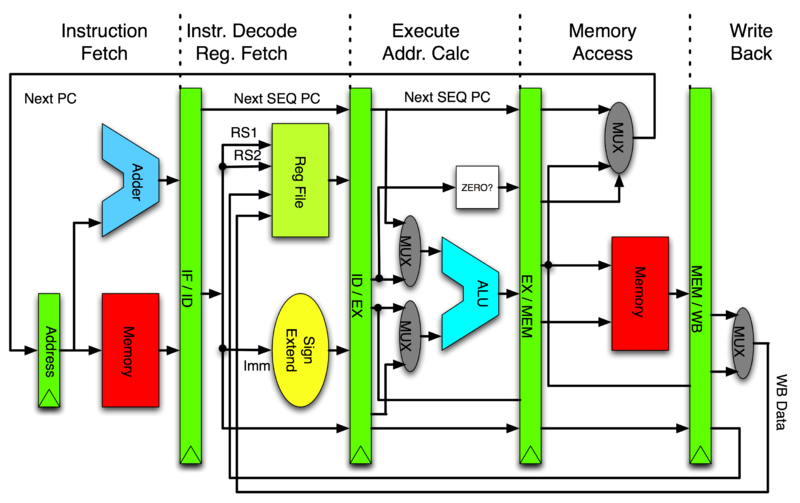
[](https://commons.wikimedia.org/wiki/File:Pipeline_MIPS.png)[https://commons.wikimedia.org/wiki/File:Pipeline_MIPS.png](https://commons.wikimedia.org/wiki/File:Pipeline_MIPS.png)
* 如上面所說 PC 指向正在執行的後 2 條指令 (+8),但若某道正在執行指令遇到中斷,這時候的 PC 會如何變化?
* 這個問題要分兩個面向來答覆,一個是 interrupt 的處理機制,另一個則是 PC 的計算方式
* 引述《[The Definitive Guide to the ARM Cortex-M3](https://www.eecs.umich.edu/courses/eecs373/labs/refs/M3%20Guide.pdf) 》Page 287:
* "Interrupt handler and interrupt return: In the ARM7, the first instruction of the interrupt handler is in the vector table, which normally contains a branch instruction to the actual interrupt handler. In the Cortex-M3, this step is no longer needed. For interrupt returns, the ARM7 relies on manual adjustment of the return program counter. In the Cortex-M3, the correctly adjusted program counter is saved into the stack and the interrupt return is triggered by loading EXC_RETURN into the program counter. Instructions, such as MOVS and SUBS, should not be used as interrupt returns on the Cortex-M3\. Because of these differences, interrupt handlers and interrupt return codes need modification during porting."
* 以 ARM Cortex-M3/M4 來說,不再需要像 ARM7 那樣手動調整返回的 program counter 值,而是以 Cortex-M 硬體給定 `EXC_RETURN` 作為新的 program counter,過程中<u>原有的 pc 值會由硬體重新計算</u>,一旦返回到原有程式時,仍以 +4/+8 (ARM) 作為位移量
* 學組語的目的,不見得是為了改善效能,而是:
* 判斷 optimizing compiler 產生的機械碼是否正確
* gcc 和 clang/llvm 引入大量的最佳化技術,已很難光看原始程式碼,去推知最終生成的機械碼
* 從 Google 搜尋偷到的程式是否有效益 (千萬不要人云亦云,要有判斷能力)
_( 11:00-12:00 )_
**[ [Introduction to ARM Architecture](https://docs.google.com/presentation/d/1cFBRICktpVQAOLzE5eDKD-OM4ckJuncFsn39Wg8aLZI/edit#slide=id.p14) ]**
- [ ] ==[程式練習](https://hackmd.io/s/HkcOofY2x)==
* [p. 4](https://docs.google.com/presentation/d/1cFBRICktpVQAOLzE5eDKD-OM4ckJuncFsn39Wg8aLZI/edit#slide=id.p25)
* objdump
* 可以顯示所有的object file的資訊
* 支援格式非常多: ELF, a.out
* 是 GNU Toolchain 一部分, 可以反組譯
* 使用時要指定架構,如: _arm-linux-gnueabihf-objdump_)
* objdump 和 readelf 相輔相成,可以做到類似的功能,但做法不同(底層library實作不同): BFD
* 可以用兩個不同工具產生的結果來互相對照
* <main> -> C語言的進入點
* 但要有一個人跳進去執行他,所以是從 ELF <start>開始在跳到 <main> => crt (C runtime)
* 不知如何用 `objdump` 得到類似結果? 試了幾種參數感覺跟投影片上都有落差
* 使用 objdump -D 可以得到部份[相似內容](https://embedded2015.hackpad.com/objdump-test-5fD74TMv0Fc)
* -D = disassembler
* 因為可能有最佳化
* -j 看 text section
* [p. 5](https://docs.google.com/presentation/d/1cFBRICktpVQAOLzE5eDKD-OM4ckJuncFsn39Wg8aLZI/edit#slide=id.p26)
* Versatile Express board with Cortex-A9 (ARMv7) core will be “emulated” using [Linaro](https://www.linaro.org/) builds.
* Versatile Express board 是 ?
* Versatile Express 是 ARM 提供的開發硬體(讓客戶廠商的參考硬體),價格較高(19萬~3X萬 NTD),但ARM官方正式支援,而且 QEMU 也支援
* "Fast Model", "Foundation Model" (ARM Ltd.) -> cycle-accurate simulation
* [Linaro](https://www.linaro.org/) 有維護 QEMU,專門開發 Open Source的公司
* ARM 不是純粹的的RISC
* 會因為客戶去改變設計,如針對 Nokia 設計出 Thumb 指令集,透過 16 位元的編碼,仍是 32 位元的處理器
* QEMU模擬的時間不是 Cycle accurate
* Cycle accurate: Load、Store、Add、Sub 執行的Cycle數會跟理論上的不一樣
* 所以 Benchmark 會不精確,只能看到趨勢變化
* 需要真正硬體才能得知正確效能
* _"Fast Model", "Foundation Model" (ARM Ltd.) -> cycle-accurate simulation _
* [p. 7](https://docs.google.com/presentation/d/1cFBRICktpVQAOLzE5eDKD-OM4ckJuncFsn39Wg8aLZI/edit#slide=id.p30)
* **為什麼Variable cycle instructions (LD/STR multiple)可以提高效能?**
* –Auto-increment/decrement addressing modes
* 這個的意思是?
* 後面會提到 STM 跟 LDM 的東西,那時候會有介紹
* ARMv8 (64-bit) 移除 LD/STR mutiple
* 有 LD/STR 跟 3 stage pipeline 變成 5 stage pipeline 有關
* 增加了 MEM、WB
* 因為記憶體開銷實在太大
* 一般 LD/STR 2個 Clock cycle
* LD/STR multiple 4個 Clock cycle
* 一次做很多個 LD/STR
* 提升程式碼密度
* 但花的時間可能差不多
* pipeline 設計的好 ,multiple LD/STR 就能發揮效益
* _ARMv8 (64-bit) 移除 LD/STR mutiple,因為要考量到 Prediction,一a次失敗會浪費掉太多資源_
* [p. 8](https://docs.google.com/presentation/d/1cFBRICktpVQAOLzE5eDKD-OM4ckJuncFsn39Wg8aLZI/edit#slide=id.p32)
* 在[ARM系統開發者指南](http://www.books.com.tw/products/0010312252)中將 exception modes 翻譯成`處理器模式`,感覺跟 exception 這個字的意思差很多,不知怎麼翻譯成處理器模式的 ?
* CPU modes, exception modes, processor modes 對ARM來講都是一模一樣
* [ARM wiki](https://en.wikipedia.org/wiki/ARM_architecture#CPU_modes) 是寫 CPU modes 還是這邊的 exception modes不是指 CPU modes?
* 以 ARM 來說,會導致 CPU 變更 execution mode 改變,就是 exception 使然,所以等價,當然,如果我們可用同樣的術語,對簡報陳述較好
* ARM切換不同模式會 exception
* 5 SPSR
* spsr_fiq, spsr_irq, spsr_svc, spsr_undef, spsr_abt
* Several exception modes
* User mode, FIQ mode, IRQ mode, Supervisor (svc) mode, Abort mode, Undefined mode, System mode
* Monitor mode, Hypervisor mode (ARMv6, ARMv7 之後)
* 模式數量會隨著版本改變
* ARMv6 之後支援多核心
* 簡報是 ARMv4, ARMv5
* [p. 9](https://docs.google.com/presentation/d/1cFBRICktpVQAOLzE5eDKD-OM4ckJuncFsn39Wg8aLZI/edit#slide=id.p33)
* context switch -> reserve/restore registers (GPR)
* context switch 要保存暫存器
* 為了降低 context switch 成本,ARM降低通用暫存器的數量
* AAPCS, ATPCS
* Function vs. Proc
* g(x), f(x) (g of f)(x); Proc 是退化的 func,對應到 ISA 的 branch/jump
* e.g. C 語言只能 return一個值
* procedure輸出域很窄
* function 有輸入域和輸出域
* R12 or IP is not instruction pointer, it is the intra procedural call scratch register
* **在[ARM系統開發者指南](http://www.books.com.tw/products/0010312252)中 r0~r12 似乎沒有特殊功能,是書中沒寫到還是後來ARM新增了?**
* EX : R10 (SL), r11 (FP), r12 (IP)
* 所以 R12: intra procedural call scratch register 的功用是? (待查)
* 保存要跳躍的範圍
* [](http://blog.csdn.net/gooogleman/article/details/3529413)[http://blog.csdn.net/gooogleman/article/details/3529413](http://blog.csdn.net/gooogleman/article/details/3529413)
* 返回值會存在 R0
* [p. 11 ](https://docs.google.com/presentation/d/1cFBRICktpVQAOLzE5eDKD-OM4ckJuncFsn39Wg8aLZI/edit#slide=id.p35)ARM vs. x86
* 補了一下計組 [Endianness](https://en.wikipedia.org/wiki/Endianness) 的知識... [Endianness](https://en.wikipedia.org/wiki/Endianness) = 一個資料(32-bit)放在記憶體中的方式
* ARM Instructions are little endian (except on the –R profile for ARMv7 where it is implementation defined)
* [p. 26](https://docs.google.com/presentation/d/1cFBRICktpVQAOLzE5eDKD-OM4ckJuncFsn39Wg8aLZI/edit#slide=id.p59) Conditional Flags
* **V 和 Q 差在哪裡?? **
* V – Overflow flag
* Q – Sticky overflow
* [](http://stackoverflow.com/questions/19557338/importance-of-qsaturation-flag-in-arm)[http://stackoverflow.com/questions/19557338/importance-of-qsaturation-flag-in-arm](http://stackoverflow.com/questions/19557338/importance-of-qsaturation-flag-in-arm)
* 簡而言之就是飽和操作如果遇到 overflow 則會讓 Q = 1
* [p. 29](https://docs.google.com/presentation/d/1cFBRICktpVQAOLzE5eDKD-OM4ckJuncFsn39Wg8aLZI/edit#slide=id.p63) PUSH operation

* stack pointer 是紀錄堆疊最後的位置
* [p. 32](https://docs.google.com/presentation/d/1cFBRICktpVQAOLzE5eDKD-OM4ckJuncFsn39Wg8aLZI/edit#slide=id.p67)
* sbc r0, r0, r1
* means: r0 = r0 - r1 - NOT(C)
* `- NOT(C) `怎麼做? 為什麼 After Operation CPSR 沒有變化?
* `- NOT(C) 怎麼做` 是什麼意思?
* ARM 需要在指令後面加上 s 才會更新 Flag
* 例如: sub r1, 0
* 跟 subs r1, 0 <--這個才會修改 flag
* 請參考: [](http://infocenter.arm.com/help/index.jsp?topic=/com.arm.doc.dui0068b/CIHCJFJG.html)[http://infocenter.arm.com/help/index.jsp?topic=/com.arm.doc.dui0068b/CIHCJFJG.html](http://infocenter.arm.com/help/index.jsp?topic=/com.arm.doc.dui0068b/CIHCJFJG.html)
* [p. 37](https://docs.google.com/presentation/d/1cFBRICktpVQAOLzE5eDKD-OM4ckJuncFsn39Wg8aLZI/edit#slide=id.p72) 的重點在? 看不出來上下兩個指令有甚麼差別在這頁有甚麼差別
* 有號無號對於乘除是個大問題,不能像加減法用 2’s complement 跟 Flag 輕鬆解決
* [p. 39 ](https://docs.google.com/presentation/d/1cFBRICktpVQAOLzE5eDKD-OM4ckJuncFsn39Wg8aLZI/edit#slide=id.p75)
* $ objdump -d helloworld | less
* 可改為 $arm-linux-gnueabihf-objdump -d helloworld | less,即可順利跑出結果
* [p. 43](https://docs.google.com/presentation/d/1cFBRICktpVQAOLzE5eDKD-OM4ckJuncFsn39Wg8aLZI/edit#slide=id.p78) **last bit off right is Carry 這句話是最後一個向右移的位元是進位?**
* [ 16bit ] [c]
* 0101010101010101 0
* ROR 1
* 1010101010101010 1
* 最後一個 bit 會被送到 carry flag,也會放到最左邊的 bit 上
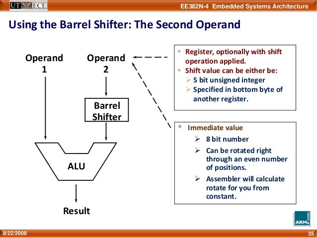
* Barrel Shifter 可提升程式碼密度 (空間複雜度)
* 如: 某數 * 3 => ADD R0, R1, R1, LSL #1 means R0=R1+(R1<<1)
* ARM 的最佳化可能會對齊到 2 的 N 次方 +1
* [p. 44](https://docs.google.com/presentation/d/1cFBRICktpVQAOLzE5eDKD-OM4ckJuncFsn39Wg8aLZI/edit#slide=id.p80) RTFM = **R**ead **T**he **F***cking **M**anual
* [Jserv’s blog: 對自己好一些:談技術手冊閱讀](http://blog.linux.org.tw/~jserv/archives/002008.html)
* 要努力找到第一手資料,以確保資料的正確性
* [p. 47](https://docs.google.com/presentation/d/1cFBRICktpVQAOLzE5eDKD-OM4ckJuncFsn39Wg8aLZI/edit#slide=id.p83) **ASR 如何運作**
* LDR -> [](http://infocenter.arm.com/help/index.jsp?topic=/com.arm.doc.dui0041c/Babbfdih.html)[http://infocenter.arm.com/help/index.jsp?topic=/com.arm.doc.dui0041c/Babbfdih.html](http://infocenter.arm.com/help/index.jsp?topic=/com.arm.doc.dui0041c/Babbfdih.html)
* asrs r0, r0, #1
* p. 43 ASR – Arithmetic Shift Right (MSB copied at left, last bit off right is Carry)
* MSB 是?
* most significant bit 最高位的 bit
* ASR,MSB 保持不變,其他 bit 向右 shift
* 可以用 QEMU + GDB 進行單步執行
* 用 objdump 去看 machine code
* 對 compiler 可以設定參數,進行最佳化
* asr 可以當成是有號的右移,等於是有號的 2^n 除法
* 在右移的時候,左邊補進來的數字也會是有號的,於是正數還是正,負依舊是負
* 而在此圖的案例當中,必須要用 2’s complement 來探討
* add.w r0,r0,r0,lsr #31
* asrs r0,r0,#1
* 為什麼要先做 add.w r0,r0,r0,lsr #31 ?
* 意思是指先把自己跟自己的 sign 相加,也就是如果是負數,就加一,正數則不變
* 這要從二的補數來看,當你右移 #1 之後,相當於除以二
* 此時最右邊的那個 bit 是 "直接消失" 對於正數不會有任何影響
* 但對於負數來說等於是多進了一位,假設以下例子
* -3 / 2 ===> 1101 >> 1 (asr) , answer = 1110 = -2
* 因為二補數表示法的負數相當於"與 0 的距離"
* 所以對於負的奇數來說
* 消失的最右邊那個bit,等於是間接幫他進位(與 0 的距離變大)ex. -3 ==> -4
* 因此必須要先做 add.w r0,r0,r0,lsr #31 來消除掉這個進位
* -3 / 2 ===> (-3+1)/2 ===> 1110 >> 1 (asr) , answer = 1111 = -1
* 結論就是compiler太聰明了!
* 為什麼Lab38中 example 3 執行完會是0?
* HINT:因為 -6 和 8 是往右位移,不是真的除2
* 可以到Makefile中把 -O3 改成 -O0,_objdump出來的結果會比較看得懂(因為關掉最佳化)_
* -O3 會在編譯階段就知道值(答案)了
* 最佳化關掉和打開都會得到 0
* [p. 48 ](https://docs.google.com/presentation/d/1cFBRICktpVQAOLzE5eDKD-OM4ckJuncFsn39Wg8aLZI/edit#slide=id.p84)**RRX 如何運作**
* mvn r0, r0, RRX
* p. 43 RRX – Rotate Right with Extend (bits popped off the right end first go into Carry, Carry is shifted in to left, last bit off right is Carry)
* [c] [ 8bit ]
* 1 01010100
* RRX 1
* [c] [ 8bit ]
* 0 10101010
* 把 c 加入,上圖所示,把 8bit 用 c 延長成 9bit 再去 rotate
* [p. 50](https://docs.google.com/presentation/d/1cFBRICktpVQAOLzE5eDKD-OM4ckJuncFsn39Wg8aLZI/edit#slide=id.p86) movw ??
* `movw` followed by a `movt` is a common way to load a 32-bit value into a register.
* 比較新的指令集才有,跟ARM版本有關(ARMv7)
* -> [](http://community.arm.com/groups/processors/blog/2010/07/27/how-to-load-constants-in-assembly-for-arm-architecture)[http://community.arm.com/groups/processors/blog/2010/07/27/how-to-load-constants-in-assembly-for-arm-architecture](http://community.arm.com/groups/processors/blog/2010/07/27/how-to-load-constants-in-assembly-for-arm-architecture)
* p. 93 STMDB equals to push operation
* p. 94 LDMIA euals to pop operation
* ex. in fib.s
* use `stmdb sp!, {r4, r5, lr}` instead of `push {r4, r5, lr}`
* and `ldmia sp!, {r4, r5, lr}` instead of `pop {r4, r5, lr}`
p.121 gdb arm 的 objectfile 有需要注意的事項嗎?
* ` gdb example1`, `b main`, `r` then I get warning: Unable to find dynamic linker breakpoint function.
* GDB will be unable to debug shared library initializers
* gdb gcc出來的code倒是可以正常 break
* 如果你的 `example1` 是 arm binary, 你應該無法這樣執行才對 (除非你的 Linux Distro 有對 binfmt 作些設定)
* 謝謝! It works like a charm!! 我在step2用`gdb-multiarch`也行的樣子(不知為何沒有裝到`arm-linux-gnueabihf-gdb`
* 剛看一下 gdb 編譯參數,他可以加上 `--enable-targets=all` 這個選項,我想你用的 linux distro 應該是編譯 gdb 時有打開這個參數,所以就不需要 `arm-linux-gnueabihf-gdb` 了
* 感謝! so上有說到[這個](http://stackoverflow.com/questions/25143757/arm-linux-gnueabihf-gdb-versus-gdb-multiarch), 跟我用的distro有關(lubuntu 15.04)
* 針對 qemu-user 執行的程式使用 gdb
* step1: `qemu-arm -L /usr/arm-linux-gnueabihf -g 1234 ./example1`
* step2: open another terminal B, enter `arm-linux-gnueabihf-gdb` or `gdb-multiarch`
* step3: In terminal B, enter `file example1`
* step4: In terminal B, enter `target remote [localhost]:1234`
* step5: enter `c` to continue program or add your breakpoint, e.g. `b main`
 Sign in with Wallet


