---
tags: fabacademy, esp, mdef, workshops
---
# ESP8266
[TOC]
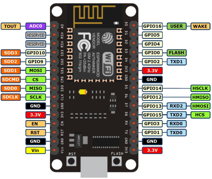
## Pinout
Remember the numbers to use are the ones after _GPIO_ (ej pin 2 is _GPIO2_) you can also use the _defined_ name of the pin (ej defined name D4 is _GPIO2_):
* **D4** = GPIO_2 = **2**
* **D5** = GPIO_14 = **14**, etc...
## Using Arduino IDE
Install ESP8266 board in arduino IDE adding this address on _Aditional Board manager URL's_ window on the _preferences_ menu item:
`http://arduino.esp8266.com/stable/package_esp8266com_index.json`

Install **ESP8266 board** in Arduino _Board Manager_:

You should now see the ESP8266 board in your Arduino Boards menu.
Select **NODE MCU** on the `Tools / Ports` menu.

## Installing the Drivers
:::warning
:warning: We found some computers (OSX and some windows versions) need an extra step for the board to be recognize.
:::
Go to the page below and look for the Driver that matches your operative system.
https://www.silabs.com/products/development-tools/software/usb-to-uart-bridge-vcp-drivers
If you have one of the bigger boards that says _LoLin_ on the back use this driver instead:
https://sparks.gogo.co.nz/ch340.html
Download and install them as any other software. Sometimes is necessesary rebooting the machine
Now you should another port on your `Tools / Ports` menu.

## Test the board
1. Load the `Files -> Examples -> ESP8266 -> Blink` example
2. For faster uploads you can select the maximum speed on the _tools -> Upload Speed_ menu.
3. Select the right USB port on the _tools -> port_ menu.
4. Click the **UPLOAD** button and wait for the process to finish.

If everything works fine your ESP8266 should be blinkig!
## Input/Output
Digital input/output can be used on all GPIO.
### DigitalWrite
```clike
void setup() {
pinMode(BUILTIN_LED, OUTPUT); // Initialize the BUILTIN_LED pin as an output
}
// the loop function runs over and over again forever
void loop() {
digitalWrite(BUILTIN_LED, LOW); // Turn the LED on (Note that LOW is the voltage level
// but actually the LED is on; this is because
// it is acive low on the ESP-01)
delay(1000); // Wait for a second
digitalWrite(BUILTIN_LED, HIGH); // Turn the LED off by making the voltage HIGH
delay(2000); // Wait for two seconds (to demonstrate the active low LED)
}
```
### DigitalRead
```clike
// You can try a digital input with a push button connected to pin D4 (GPIO 2)
int pushButton = D4;
// the setup routine runs once when you press reset:
void setup() {
// initialize serial communication at 9600 bits per second:
Serial.begin(9600);
// make the pushbutton's pin an input and activate the internal pullup resistor:
pinMode(pushButton, INPUT_PULLUP);
}
// the loop routine runs over and over again forever:
void loop() {
// read the input pin:
int buttonState = digitalRead(pushButton);
// print out the state of the button:
Serial.println(buttonState);
delay(1); // delay in between reads for stability
}
```
### AnalogRead
Esp8266 **only has one analog** channel that can be used on pin A0.
```clike
// the setup routine runs once when you press reset:
void setup() {
// initialize serial communication at 9600 bits per second:
Serial.begin(9600);
}
// the loop routine runs over and over again forever:
void loop() {
// read the input on analog pin 0:
int sensorValue = analogRead(A0);
// print out the value you read:
Serial.println(sensorValue);
delay(1); // delay in between reads for stability
}
```
### AnalogWrite
PWM has a resolution of 10 bits (1024 values) at 1kHz and can be used on pins D2, D5, D6 and D8:
```clike
int led = D4; // the PWM pin the LED is attached to
int brightness = 0; // how bright the LED is
int fadeAmount = 5; // how many points to fade the LED by
// the setup routine runs once when you press reset:
void setup() {
// declare pin to be an output:
pinMode(led, OUTPUT);
}
// the loop routine runs over and over again forever:
void loop() {
// set the brightness:
analogWrite(led, brightness);
// change the brightness for next time through the loop:
brightness = brightness + fadeAmount;
// reverse the direction of the fading at the ends of the fade:
if (brightness <= 0 || brightness >= 255) {
fadeAmount = -fadeAmount;
}
// wait for 30 milliseconds to see the dimming effect
delay(30);
}
```
## WiFi
File -> Examples -> ESP8266WiFi -> WiFiClient
```clike
#include <ESP8266WiFi.h>
const char* ssid = "your-ssid";
const char* password = "your-password";
void setup() {
Serial.begin(115200);
delay(10);
Serial.println();
Serial.print("Connecting to ");
Serial.println(ssid);
WiFi.begin(ssid, password);
while (WiFi.status() != WL_CONNECTED) {
delay(500);
Serial.print(".");
}
Serial.println("");
Serial.println("WiFi connected");
Serial.println("IP address: ");
Serial.println(WiFi.localIP());
}
void loop() {
}
```
> This is mostly similar to WiFi shield library. Differences include:
>WiFi.mode(m): set mode to WIFI_AP, WIFI_STA, WIFI_AP_STA or WIFI_OFF.
call WiFi.softAP(ssid) to set up an open network
call WiFi.softAP(ssid, password) to set up a WPA2-PSK network (password should be at least 8 characters)
WiFi.macAddress(mac) is for STA, WiFi.softAPmacAddress(mac) is for AP.
WiFi.localIP() is for STA, WiFi.softAPIP() is for AP.
>WiFi.printDiag(Serial) will print out some diagnostic info
WiFiUDP class supports sending and receiving multicast packets on STA interface. When sending a multicast packet, replace udp.beginPacket(addr, port) with udp.beginPacketMulticast(addr, port, WiFi.localIP()). When listening to multicast packets, replace udp.begin(port) with udp.beginMulticast(WiFi.localIP(), multicast_ip_addr, port). You can use udp.destinationIP() to tell whether the packet received was sent to the multicast or unicast address.
> WiFiServer, WiFiClient, and WiFiUDP behave mostly the same way as with WiFi shield library. Four samples are provided for this library. You can see more commands here: http://www.arduino.cc/en/Reference/WiFi
>
## Installing a library
To open the Arduino library manager go to:
_Sketch → Include Library → Manage libraries._

There you can search and install all kind of libraries.
___
:::info
**Useful references**
[ESP8266 Arduino Core reference](http://esp8266.github.io/Arduino/versions/2.0.0-rc2/doc/reference.html)
:::
 Sign in with Wallet


