# Digirule 2U User Manual
30 April 2022
---
## Description
The Digirule 2U is an Open Source Hardware programmable 8-bit binary computer built into a 20 cm (8”) PCB ruler.
Full details can be found here: bradsprojects.com/digirule2
## Features and Specifications
- Microchip PIC18F46K20 8-bit microcontroller
- USB-C interface with FTDI FT234XD virtual-COM port controller
- 8-bit address bus
- 8-bit data bus
- 8-bit Program Counter register
- 8-bit Accumulator register
- 8-bit Status register (memory mapped)
- 64-level stack
- 256 bytes program/data RAM (4 bytes reserved for registers)
- Eight non-volatile memory files to back up your programs
- 54 instructions
- Adjustable instruction execution interval (speed)
- Eight Address LEDs, eight Data LEDs, Run and Stop LEDs
- Eight Data input buttons
- File Load and Save buttons
- Address Goto, Previous and Next buttons
- Data Store button
- CPU Run/Stop button
- Built-in Debug Monitor
- Built-in Firmware Updater
- Expansion Port with UART, Pin I/O and ICSP interfaces
- Powered by 3-volt CR2032 coin cell battery
- Instruction set reference chart
- Dimensions: 210 mm (8.27") L x 40 mm (1.57") W x 7 mm (0.28") H
- Weight: 37 grams (1.3 oz) including battery
## Overview
### Front Side
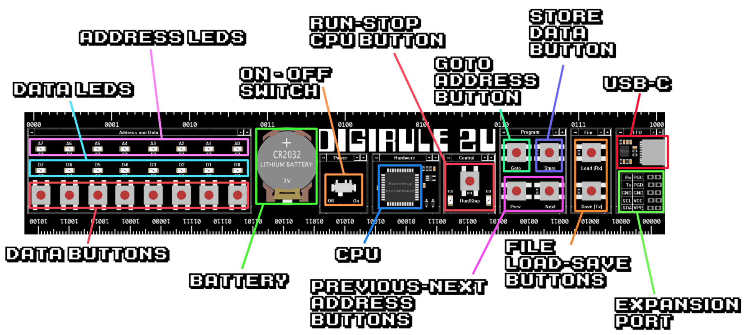
The front of the Digirule 2U contains the battery, power switch, microcontroller, buttons, LEDs, USB-C port and Expansion Port.
### Rear Side
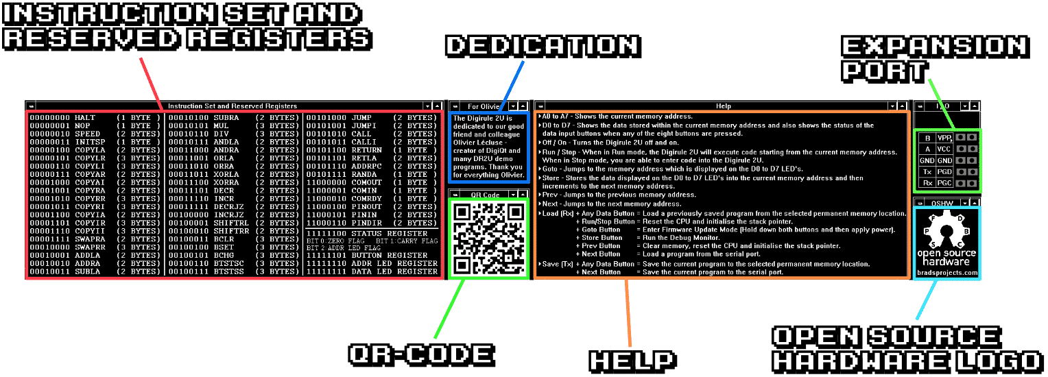
The rear of the Digirule 2U contains a chart of the instruction set and reserved registers, and a Help section. It also features an Open Source Hardware logo and a QR-Code which will take you to the Digirule 2 webpage. The Expansion Port is also accessible. And finally, a dedication to our good friend *Olivier Lecluse*, who was a great help to us in the development of the Digirule 2U.
## History
The Digirule 2U is the third edition of the Digirule 2 series of portable computers. The first was the Digirule 2, while the second was the Digirule 2A. The Digirule 2U represents a significant hardware and software upgrade compared to the previous versions.
The Digirule 2U differs from its predecessor (the Digirule 2A) in the following ways:
* PIC18F46K20 microcontroller (Digirule 2A uses PIC18F45K20 microcontroller)
* Microcontroller clock speed is 16 MHz (Digirule 2A microcontroller clock speed is 8 MHz)
* USB-C and UART communications interfaces
* Expansion Port
* 54 instructions, including multiply and divide (Digirule 2A has 35 instructions)
* COPYxx instructions now update the Zero status flag
* ADDxx and SUBxx instructions now include the Carry status flag in their calculation
* RANDA instruction has been significantly improved
* CPU performance has been significantly improved
* CPU stack depth is 64 (Digirule 2A stack depth is 4)
* Built-in Debug Monitor
* Built-in Firmware Updater
* Supported by full-featured *adr2* assembler and *udr2* firmware updater
---
## Conventions Used in This Manual
Most numbers are presented in both hexadecimal and binary, using the following notation:
- 0xA5 (10100101)
Some small numbers (for example *bit* numbers) are presented in decimal and binary:
- 7 (00000111)
---
## Operation
### Getting Started
It is important that care be taken when installing the CR2032 battery. First make sure the battery's positive side is facing ***up*** (away from the Digirule 2U) and the battery is slotted ***under*** the metal tab at the front of the holder. Then press down on the ***opposite*** end of the battery until it snaps under the plastic retaining tabs. Failure to follow this procedure may result in damage to the battery holder.

The power switch turns the Digirule 2U on or off when using the battery as the power source. The Digirule 2U is *always* on when connected to a USB power source, regardless of the power switch setting.
When powered on, the Digirule 2U performs a brief LED animation so you can verify all of the LEDs are functioning. RAM is cleared and the CPU is reset. The Digirule 2U is now ready for use.
### Modes of Operation
The Digirule 2U is in one of the following five modes of operation at any point in time:
#### Stop Mode
This is the mode from which most of the Digirule 2U functions are accessed. In this mode, the **Stop** LED is on and the CPU is stopped, and you can:
| Action | Steps |
| - | - |
| Clear RAM | Press *and hold* the **Load** button, then press the **Prev** button. |
| Edit RAM | Use the **Data**, **Goto**, **Prev**, **Next** and **Store** buttons. |
| Load RAM from a non-volatile memory file | Press *and hold* the **Load** button, then press a **Data** button. |
| Save RAM to a non-volatile memory file | Press *and hold* the **Save** button, then press a **Data** button. |
| Load RAM from the Comm Port | Press *and hold* the **Load** button, then press the **Next** button. The Digirule 2U enters **Comm Load** mode. |
| Save RAM to the Comm Port | Press *and hold* the **Save** button, then press the **Next** button. The Digirule 2U enters **Comm Save** mode. |
| Reset the CPU | Press *and hold* the **Load** button, then press the **Run/Stop** button. |
| Start the CPU | Press the **Run/Stop** button. The Digirule 2U enters **Run** mode. |
| Start the Debug Monitor | Press *and hold* the **Load** button, then press the **Store** button. The Digirule 2U enters **Monitor** mode. |
The Address LEDs display the contents of the Program Counter. The Data LEDs display the contents of RAM addressed by the Program Counter.
#### Run Mode
In this mode, the **Run** LED is on and the CPU is executing instructions, and you can:
| Action | Steps |
| - | - |
| Provide input to the program | Press any **Data** button(s). |
| Turn on or off the Address LEDs | Press the **Goto** button. |
| Stop the CPU | Press the **Run/Stop** button. The Digirule 2U enters **Stop** mode. |
Unless turned off, the Address LEDs display the contents of the Program Counter (if bit 2 of the Status Register is clear) or the contents of the Address LEDs Register (if bit 2 of the Status Register is set). The Data LEDs display the contents of the Data LEDs Register.
#### Comm Load Mode
In this mode, RAM is loaded with data (in *Intel Hex* format) from the Comm Port. The Address LEDs display a progress bar. The Data LEDs display status as follows:
| LED | Meaning |
| - | - |
| D7 | Listening status (blinking) |
| D6-D3 | |
| D2 | Record type error |
| D1 | Checksum error |
| D0 | Non-hex character error |
When the data has been fully received, the *Listening* status LED stops blinking. If an error occurred, the error LED starts blinking, and you need to press any **Data** button to clear the error condition. The Digirule 2U then automatically resets the CPU, sets the Program Counter to the entry point of the program, and enters **Stop** mode.
This mode can be cancelled by pressing the **Run/Stop** button, and the Digirule 2U enters **Stop** mode.
> Note: The Comm Port configuration is 9600 baud, 8 data bits, no parity, 1 stop bit.
#### Comm Save Mode
In this mode, RAM is saved (in *Intel Hex* format) to the Comm Port. The Address LEDs display a progress bar. The Data LEDs display status as follows:
| LED | Meaning |
| - | - |
| D7 | |
| D6 | Talking status (blinking) |
| D5-D0 | |
When the data has been fully transmitted, the *Talking* status LED stops blinking, and the Digirule 2U enters **Stop** mode.
This mode can be cancelled by pressing the **Run/Stop** button, and the Digirule 2U enters **Stop** mode.
> Note: The Comm Port configuration is 9600 baud, 8 data bits, no parity, 1 stop bit.
#### Monitor Mode
In this mode, the built-in Debug Monitor is active on the Comm Port. See the *Using the Debug Monitor* section for information on how to use the monitor.
This mode can be cancelled by pressing the **Run/Stop** button, and the Digirule 2U enters **Stop** mode.
---
### Entering a Program
With the Digirule 2U in **Stop** mode, you can enter a program into RAM using the eight **Data** buttons and the four **Program** window buttons. The Program Counter contains the address of (points to) the RAM location currently being edited, and is displayed on the Address LEDs. The contents of the addressed RAM location is displayed on the Data LEDs. Refer to the handy chart on the rear of the Digirule 2U to find opcode values for specific instructions.
> Tip: To quickly fill all of RAM with zeros, press *and hold* the **Load** button, then press the **Prev** button.
To modify the value displayed on the Data LEDs, press the button below the particular LED whose state you want to change. If the LED is off, pressing the corresponding button turns it on, and vice-versa.
> Tip: To quickly fill all of the Data LEDs with zeros, press *and hold* the **Data 0** button for one second. To fill all of the Data LEDs with ones, press *and hold* the **Data 7** button for one second.
To set the Program Counter (RAM address), first enter the address on the Data LEDs, then press the **Goto** button to transfer it to the Program Counter (and the Address LEDs). The contents of the RAM location addressed by the Program Counter is displayed on the Data LEDs. Alternatively, you can use the **Prev** and **Next** buttons to decrement or increment the Program Counter by one with each press of the button.
Once the Program Counter is set to the desired address, you can then modify the contents of that RAM location by first editing the value displayed on the Data LEDs, then pressing the **Store** button to write that value to RAM. The Program Counter is automatically incremented to the next address. Use the **Prev** and **Next** buttons as desired to review any changes. Repeat this process to enter the rest of your program, then you can run it.
### Running and Stopping a Program
With the Digirule 2U in **Stop** mode, first make sure the Program Counter (displayed on the Address LEDs) contains the start address (typically 0x00) of the program you want to run, then press the **Run/Stop** button to start the program. The **Stop** LED turns off and the **Run** LED turns on, indicating the Digirule 2U is now in **Run** mode.
> Tip: You can start a program at any address you want. In fact, you can have multiple programs loaded in RAM at the same time, at different addresses. For example, you could have one program at addresses 0x00 to 0x3F and another at addresses 0x40 to 0x7F. To run the first program, set the Program Counter to 0x00 (00000000), then press the **Run/Stop** button. To run the second program, set the Program Counter to 0x40 (01000000), then press the **Run/Stop** button.
While in **Run** mode, the Address LEDs display (by default) the constantly changing address in the Program Counter as the CPU executes instructions. In some cases, this can be a distraction. You can hide this display if desired by pressing the **Goto** button. To show the display again, press the **Goto** button again.
To stop a running program, press the **Run/Stop** button. The **Run** LED turns off and the **Stop** LED turns on, indicating the Digirule 2U is now in **Stop** mode. The internal state of the CPU and all memory and registers is retained. The Program Counter is left pointing to the next instruction to be executed. To resume execution of the program from that point, press the **Run/Stop** button again. If instead you want to restart the program from the beginning, reset the CPU by first pressing *and holding* the **Load** button, then press the **Run/Stop** button. Then release both buttons, and press the **Run/Stop** button again to start the program (at address 0x00).
> Tip: In some cases you can safely restart a program by simply setting the Program Counter back to the start address and pressing the **Run/Stop** button. However this method does not reset certain CPU resources back to their default states, so your program may not function as intended. If your program uses the `SPEED` instruction, the `CALL` and `RETURN` instructions (i.e. the stack), or the `PIN` instructions, you may want to reset the CPU instead.
The CPU will automatically halt and the Digirule 2U enters **Stop** mode in the following circumstances:
* A stack overflow occurs (`CALL` instruction is executed with full stack)
* A stack underflow occurs (`RETURN` instruction is executed with empty stack)
* A `DIV` instruction is executed with zero divisor
* A `HALT` instruction is executed
* An invalid instruction opcode is fetched
### Saving and Loading a Program
With the Digirule 2U in **Stop** mode, you can save the current contents of RAM to any of eight non-volatile memory files. This will retain your program(s) even if the battery is removed. To do this, first press *and hold* the **Save** button. The Data LEDs will animate back and forth. Then press one of the eight **Data** buttons to save the current contents of RAM to that particular file. Then release both buttons.
To load RAM from a previously saved file, first press *and hold* the **Load** button. The Data LEDs will animate back and forth. Then press one of the eight **Data** buttons to load RAM from that particular file. Then release both buttons. The CPU is automatically reset, and the Program Counter is set to 0x00. If that is the correct start address for your program, simply press the **Run/Stop** button to start it.
> Tip: To copy the contents of one file to another, first load RAM from the desired source file, then save it to the desired destination file.
The Digirule 2U comes with eight sample programs preinstalled in each of the eight files.
| File | Program | Description |
| - | - | - |
| 0 | *Hello World* | Displays "Hello World!" on the terminal using ASCII art. |
| 1 | *Prime Numbers* | Calculates prime numbers to 255 and displays them on the terminal. |
| 2 | *Base Trainer* | A game that teaches binary-to-hexadecimal conversion. |
| 3 | *Logic Trainer* | A game that teaches logic gate functions. |
| 4 | *Mastermind* | A game where you guess a random 4-digit number. |
| 5 | *24-bit Up/Down Counter* | Demonstrates multi-byte addition and subtraction. The upper two bytes of the counter are visible on the Address and Data LEDs (the lower byte is not visible). Press any **Data** button to reverse the direction of the counter. |
| 6 | *Echo* | Comm loopback. Any data received from the terminal is transmitted back to the terminal, and displayed on the Data LEDs. |
| 7 | *Kill the Bit* | A game that starts with a single Data LED shifting right to left. The player needs to press any of the eight **Data** buttons in an attempt to turn off the lit LED. Pressing a button when the LED above it is on turns it off. However pressing a button when the LED is off turns it on. The goal is to turn off all of the LEDs. |
> Tip: When you save your own program to a particular file, the sample program previously stored there is deleted. However it can be restored later if desired by downloading the appropriate sample program hex file from the Digirule 2U website, downloading it to RAM via the Comm Port, and saving it to that file again.
---
## Memory-Mapped Registers
The Digirule 2U has four memory locations reserved for special purpose registers. These are located at the very top of the RAM address space.
| Register | Address | Access | Contents |
| - | - | - | - |
| Status Register | 0xFC (11111100) | Read/Write | CPU status flags. See following table. |
| Button Register | 0xFD (11111101) | Read Only | **Data** buttons status. For each bit, if that bit is set, the corresponding button is pressed. |
| Address LEDs Register | 0xFE (11111110) | Read/Write | Displayed on the Address LEDs **while in Run mode** and **only if bit 2 of the Status Register is set**. |
| Data LEDs Register | 0xFF (11111111) | Read/Write | Displayed on the Data LEDs **while in Run mode**. |
### Status Register
| Bit | Flag | Description |
| - | - | - |
| 0 | Z (*Zero*) | If set, the previous instruction produced a zero result. |
| 1 | C (*Carry*) | If set, the previous instruction produced a carry or borrow. |
| 2 | Show Address LEDs Register | If set, the Address LEDs display the contents of the Address LEDs Register **while in Run mode**. If clear, the Address LEDs display the contents of the Program Counter. |
| 3-7 | | Undefined |
---
## Instruction Set Summary
| Opcode | Instruction | Description | Bytes | Flags |
| - | - | - | - | - |
| 0x00 | `HALT` | Stop the CPU | 1 | |
| 0x01 | `NOP` | No operation | 1 | |
| 0x02 | `SPEED` | Set instruction execution interval | 2 | |
| 0x03 | `INITSP` | Initialise Stack Pointer | 1 | |
| 0x04 | `COPYLA` | Copy literal to Accumulator | 2 | Z |
| 0x05 | `COPYLR` | Copy literal to RAM | 3 | Z |
| 0x06 | `COPYLI` | Copy literal to RAM indirect | 3 | Z |
| 0x07 | `COPYAR` | Copy Accumulator to RAM | 2 | Z |
| 0x08 | `COPYAI` | Copy Accumulator to RAM indirect | 2 | Z |
| 0x09 | `COPYRA` | Copy RAM to Accumulator | 2 | Z |
| 0x0A | `COPYRR` | Copy RAM to RAM | 3 | Z |
| 0x0B | `COPYRI` | Copy RAM to RAM indirect | 3 | Z |
| 0x0C | `COPYIA` | Copy RAM indirect to Accumulator | 2 | Z |
| 0x0D | `COPYIR` | Copy RAM indirect to RAM | 3 | Z |
| 0x0E | `COPYII` | Copy RAM indirect to RAM indirect | 3 | Z |
| 0x0F | `SWAPRA` | Swap RAM with Accumulator | 2 | |
| 0x10 | `SWAPRR` | Swap RAM with RAM | 3 | |
| 0x11 | `ADDLA` | Add literal to Accumulator | 2 | Z, C |
| 0x12 | `ADDRA` | Add RAM to Accumulator | 2 | Z, C |
| 0x13 | `SUBLA` | Subtract literal from Accumulator | 2 | Z, C |
| 0x14 | `SUBRA` | Subtract RAM from Accumulator | 2 | Z, C |
| 0x15 | `MUL` | Multiply RAM with RAM | 3 | Z, C |
| 0x16 | `DIV` | Divide RAM with RAM | 3 | Z, C |
| 0x17 | `ANDLA` | AND literal with Accumulator | 2 | Z |
| 0x18 | `ANDRA` | AND RAM with Accumulator | 2 | Z |
| 0x19 | `ORLA` | OR literal with Accumulator | 2 | Z |
| 0x1A | `ORRA` | OR RAM with Accumulator | 2 | Z |
| 0x1B | `XORLA` | Exclusive-OR literal with Accumulator | 2 | Z |
| 0x1C | `XORRA` | Exclusive-OR RAM with Accumulator | 2 | Z |
| 0x1D | `DECR` | Decrement RAM | 2 | Z |
| 0x1E | `INCR` | Increment RAM | 2 | Z |
| 0x1F | `DECRJZ` | Decrement RAM, jump if zero | 2 | Z |
| 0x20 | `INCRJZ` | Increment RAM, jump if zero | 2 | Z |
| 0x21 | `SHIFTRL` | Rotate RAM left through Carry | 2 | C |
| 0x22 | `SHIFTRR` | Rotate RAM right through Carry | 2 | C |
| 0x23 | `BCLR` | Bit clear RAM | 3 | |
| 0x24 | `BSET` | Bit set RAM | 3 | |
| 0x25 | `BCHG` | Bit change RAM | 3 | |
| 0x26 | `BTSTSC` | Bit test RAM, skip if clear | 3 | |
| 0x27 | `BTSTSS` | Bit test RAM, skip if set | 3 | |
| 0x28 | `JUMP` | Jump to address | 2 | |
| 0x29 | `JUMPI` | Jump to address indirect | 2 | |
| 0x2A | `CALL` | Call subroutine | 2 | |
| 0x2B | `CALLI` | Call subroutine indirect | 2 | |
| 0x2C | `RETURN` | Return from subroutine | 1 | |
| 0x2D | `RETLA` | Return from subroutine with value | 2 | |
| 0x2E | `ADDRPC` | Add RAM to Program Counter | 2 | |
| 0x2F | `RANDA` | Pseudo-random number to Accumulator | 1 | |
| 0xC0 | `COMOUT` | Copy Accumulator to Comm Port | 1 | |
| 0xC1 | `COMIN` | Copy Comm Port to Accumulator | 1 | |
| 0xC2 | `COMRDY` | Check if Comm Port data available | 1 | Z |
| 0xC4 | `PINOUT` | Copy Accumulator to Expansion Port pin(s) | 2 | |
| 0xC5 | `PININ` | Copy Expansion Port pin(s) to Accumulator | 2 | Z |
| 0xC6 | `PINDIR` | Configure Expansion Port pin(s) direction | 2 | |
---
## Instruction Set Detail
### 0x00 `HALT`
**Description:** Stop the CPU.
**Usage:** `HALT`
**Program Bytes Used:** 1
**Status Flags Affected:** None
**Example:**
| Address Hex (Binary) | Instruction | Machine Code Hex (Binary) | Remarks |
| - | - | - | - |
| 0x00 (00000000) | `HALT` | 0x00 (00000000) | |
| 0x01 (00000001) | `JUMP` | 0x28 (00101000) | The Program Counter points here after `HALT` is executed |
> Tip: When the `HALT` instruction is executed, the Digirule 2U enters **Stop** mode, and any data written to the Address and/or Data LEDs registers by your program will no longer be displayed. If you want to effectively halt your program but keep your data displayed, use a `JUMP *` instruction instead.
> Tip: It is sometimes helpful to follow a `HALT` instruction with a `JUMP` instruction to a restart point in your program, in case the **Run/Stop** button is pressed to resume execution.
### 0x01 `NOP`
**Description:** Performs no operation.
**Usage:** `NOP`
**Program Bytes Used:** 1
**Status Flags Affected:** None
**Example:**
| Address Hex (Binary) | Instruction | Machine Code Hex (Binary) |
| - | - | - |
| 0x00 (00000000) | `NOP` | 0x01 (00000001) |
### 0x02 `SPEED`
**Description:** Set the time interval at which the CPU executes instructions. The higher the value, the longer the interval (lower the rate).
**Usage:** `SPEED value`
**Program Bytes Used:** 2
**Status Flags Affected:** None
The following table shows the possible instruction argument values and the associated instruction execution intervals. For example, using a value of 0x80 (10000000) will result in the CPU executing one instruction every 125 milliseconds, or 8 instructions per second. Omitting this instruction, or using a value of 0x00 (00000000), will result in the CPU executing instructions at the maximum possible rate.
| Value | mSec | Value | mSec | Value | mSec | Value | mSec |
| - | - | - | - | - | - | - | - |
| 0x00 | 0 | 0x40 | 52 | 0x80 | 125 | 0xC0 | 250 |
| 0x01 | 1 | 0x41 | 53 | 0x81 | 127 | 0xC1 | 253 |
| 0x02 | 2 | 0x42 | 54 | 0x82 | 128 | 0xC2 | 256 |
| 0x03 | 3 | 0x43 | 55 | 0x83 | 130 | 0xC3 | 259 |
| 0x04 | 3 | 0x44 | 56 | 0x84 | 131 | 0xC4 | 262 |
| 0x05 | 4 | 0x45 | 57 | 0x85 | 133 | 0xC5 | 265 |
| 0x06 | 5 | 0x46 | 58 | 0x86 | 134 | 0xC6 | 268 |
| 0x07 | 5 | 0x47 | 59 | 0x87 | 136 | 0xC7 | 271 |
| 0x08 | 6 | 0x48 | 60 | 0x88 | 137 | 0xC8 | 275 |
| 0x09 | 7 | 0x49 | 61 | 0x89 | 139 | 0xC9 | 278 |
| 0x0A | 8 | 0x4A | 62 | 0x8A | 140 | 0xCA | 281 |
| 0x0B | 8 | 0x4B | 63 | 0x8B | 142 | 0xCB | 285 |
| 0x0C | 9 | 0x4C | 64 | 0x8C | 143 | 0xCC | 288 |
| 0x0D | 10 | 0x4D | 65 | 0x8D | 145 | 0xCD | 291 |
| 0x0E | 11 | 0x4E | 66 | 0x8E | 146 | 0xCE | 295 |
| 0x0F | 11 | 0x4F | 67 | 0x8F | 148 | 0xCF | 299 |
| 0x10 | 12 | 0x50 | 68 | 0x90 | 150 | 0xD0 | 302 |
| 0x11 | 13 | 0x51 | 69 | 0x91 | 151 | 0xD1 | 306 |
| 0x12 | 14 | 0x52 | 70 | 0x92 | 153 | 0xD2 | 310 |
| 0x13 | 14 | 0x53 | 71 | 0x93 | 154 | 0xD3 | 314 |
| 0x14 | 15 | 0x54 | 72 | 0x94 | 156 | 0xD4 | 318 |
| 0x15 | 16 | 0x55 | 73 | 0x95 | 158 | 0xD5 | 322 |
| 0x16 | 17 | 0x56 | 74 | 0x96 | 160 | 0xD6 | 326 |
| 0x17 | 17 | 0x57 | 75 | 0x97 | 161 | 0xD7 | 331 |
| 0x18 | 18 | 0x58 | 76 | 0x98 | 163 | 0xD8 | 335 |
| 0x19 | 19 | 0x59 | 78 | 0x99 | 165 | 0xD9 | 340 |
| 0x1A | 20 | 0x5A | 79 | 0x9A | 166 | 0xDA | 345 |
| 0x1B | 21 | 0x5B | 80 | 0x9B | 168 | 0xDB | 349 |
| 0x1C | 21 | 0x5C | 81 | 0x9C | 170 | 0xDC | 354 |
| 0x1D | 22 | 0x5D | 82 | 0x9D | 172 | 0xDD | 359 |
| 0x1E | 23 | 0x5E | 83 | 0x9E | 174 | 0xDE | 365 |
| 0x1F | 24 | 0x5F | 84 | 0x9F | 176 | 0xDF | 370 |
| 0x20 | 25 | 0x60 | 85 | 0xA0 | 177 | 0xE0 | 375 |
| 0x21 | 25 | 0x61 | 86 | 0xA1 | 179 | 0xE1 | 381 |
| 0x22 | 26 | 0x62 | 88 | 0xA2 | 181 | 0xE2 | 387 |
| 0x23 | 27 | 0x63 | 89 | 0xA3 | 183 | 0xE3 | 393 |
| 0x24 | 28 | 0x64 | 90 | 0xA4 | 185 | 0xE4 | 400 |
| 0x25 | 29 | 0x65 | 91 | 0xA5 | 187 | 0xE5 | 406 |
| 0x26 | 29 | 0x66 | 92 | 0xA6 | 189 | 0xE6 | 413 |
| 0x27 | 30 | 0x67 | 93 | 0xA7 | 191 | 0xE7 | 420 |
| 0x28 | 31 | 0x68 | 95 | 0xA8 | 193 | 0xE8 | 427 |
| 0x29 | 32 | 0x69 | 96 | 0xA9 | 195 | 0xE9 | 435 |
| 0x2A | 33 | 0x6A | 97 | 0xAA | 197 | 0xEA | 443 |
| 0x2B | 34 | 0x6B | 98 | 0xAB | 199 | 0xEB | 451 |
| 0x2C | 35 | 0x6C | 99 | 0xAC | 201 | 0xEC | 460 |
| 0x2D | 35 | 0x6D | 101 | 0xAD | 204 | 0xED | 470 |
| 0x2E | 36 | 0x6E | 102 | 0xAE | 206 | 0xEE | 479 |
| 0x2F | 37 | 0x6F | 103 | 0xAF | 208 | 0xEF | 490 |
| 0x30 | 38 | 0x70 | 104 | 0xB0 | 210 | 0xF0 | 500 |
| 0x31 | 39 | 0x71 | 106 | 0xB1 | 213 | 0xF1 | 512 |
| 0x32 | 40 | 0x72 | 107 | 0xB2 | 215 | 0xF2 | 525 |
| 0x33 | 41 | 0x73 | 108 | 0xB3 | 217 | 0xF3 | 538 |
| 0x34 | 41 | 0x74 | 109 | 0xB4 | 220 | 0xF4 | 552 |
| 0x35 | 42 | 0x75 | 111 | 0xB5 | 222 | 0xF5 | 568 |
| 0x36 | 43 | 0x76 | 112 | 0xB6 | 224 | 0xF6 | 585 |
| 0x37 | 44 | 0x77 | 113 | 0xB7 | 227 | 0xF7 | 604 |
| 0x38 | 45 | 0x78 | 115 | 0xB8 | 229 | 0xF8 | 625 |
| 0x39 | 46 | 0x79 | 116 | 0xB9 | 232 | 0xF9 | 650 |
| 0x3A | 47 | 0x7A | 117 | 0xBA | 234 | 0xFA | 677 |
| 0x3B | 48 | 0x7B | 119 | 0xBB | 237 | 0xFB | 710 |
| 0x3C | 49 | 0x7C | 120 | 0xBC | 240 | 0xFC | 750 |
| 0x3D | 50 | 0x7D | 121 | 0xBD | 242 | 0xFD | 802 |
| 0x3E | 51 | 0x7E | 123 | 0xBE | 245 | 0xFE | 875 |
| 0x3F | 51 | 0x7F | 124 | 0xBF | 248 | 0xFF | 1000 |
**Example 1:** Set the interval to 125 mS (8 instructions per second).
| Address Hex (Binary) | Instruction | Machine Code Hex (Binary) |
| - | - | - |
| 0x00 (00000000) | `SPEED` | 0x02 (00000010) |
| 0x01 (00000001) | `0x80` | 0x80 (10000000) |
**Example 2:** Set the interval to 10 mS (100 instructions per second).
| Address Hex (Binary) | Instruction | Machine Code Hex (Binary) |
| - | - | - |
| 0x00 (00000000) | `SPEED` | 0x02 (00000010) |
| 0x01 (00000001) | `0x0D` | 0x0D (00001101) |
**Example 3:** Perform a one-second time delay, then resume execution at the maximum rate.
| Address Hex (Binary) | Instruction | Machine Code Hex (Binary) |
| - | - | - |
| 0x00 (00000000) | `SPEED` | 0x02 (00000010) |
| 0x01 (00000001) | `0xFF` | 0xFF (11111111) |
| 0x02 (00000010) | `SPEED` | 0x02 (00000010) |
| 0x03 (00000011) | `0x00` | 0x00 (00000000) |
### 0x03 `INITSP`
**Description:** Initialise the Stack Pointer to point to the top of the stack (i.e. empty the stack).
**Usage:** `INITSP`
**Program Bytes Used:** 1
**Status Flags Affected:** None
**Example:**
| Address Hex (Binary) | Instruction | Machine Code Hex (Binary) |
| - | - | - |
| 0x00 (00000000) | `INITSP` | 0x03 (00000011) |
> Tip: If your program uses the stack (`CALL`/`RETURN` instructions), use of this instruction (typically near the beginning of your program) is recommended. If omitted, repeatedly restarting the program by simply resetting the Program Counter may eventually lead to a stack overflow condition.
### 0x04 `COPYLA`
**Description:** Copy the literal value to the Accumulator.
**Usage:** `COPYLA lit`
**Program Bytes Used:** 2
**Status Flags Affected:** Z
**Example:** Copy the number 0x7B (01111011) to the Accumulator.
> *Pre-Conditions*:
> - Accumulator = 0x10 (00010000)
> - Z = ?
| Address Hex (Binary) | Instruction | Machine Code Hex (Binary) |
| - | - | - |
| 0x00 (00000000) | `COPYLA` | 0x04 (00000100) |
| 0x01 (00000001) | `0x7B` | 0x7B (01111011) |
> *Post-Conditions*:
> - Accumulator = 0x7B (01111011)
> - Z = 0
### 0x05 `COPYLR`
**Description:** Copy the literal value to RAM at the specified address.
**Usage:** `COPYLR lit,addr`
**Program Bytes Used:** 3
**Status Flags Affected:** Z
**Example 1:** Copy the number 0x23 (00100011) to RAM at address 0xF0 (11110000).
> *Pre-Conditions*:
> - RAM at address 0xF0 (11110000) = 0x00 (00000000)
> - Z = ?
| Address Hex (Binary) | Instruction | Machine Code Hex (Binary) |
| - | - | - |
| 0x00 (00000000) | `COPYLR` | 0x05 (00000101) |
| 0x01 (00000001) | `0x23` | 0x23 (00100011) |
| 0x02 (00000010) | `0xF0` | 0xF0 (11110000) |
> *Post-Conditions*:
> - RAM at address 0xF0 (11110000) = 0x23 (00100011)
> - Z = 0
**Example 2:** Copy the number 0x52 (01010010) to RAM at address 0xF1 (11110001).
> *Pre-Conditions*:
> - RAM at address 0xF1 (11110001) = 0x0F (00001111)
> - Z = ?
| Address Hex (Binary) | Instruction | Machine Code Hex (Binary) |
| - | - | - |
| 0x00 (00000000) | `COPYLR` | 0x05 (00000101) |
| 0x01 (00000001) | `0x52` | 0x52 (01010010) |
| 0x02 (00000010) | `0xF1` | 0xF1 (11110001) |
> *Post-Conditions*:
> - RAM at address 0xF1 (11110001) = 0x52 (01010010)
> - Z = 0
### 0x06 `COPYLI`
**Description:** Copy the literal value to RAM at the address contained in RAM at the specified address.
**Usage:** `COPYLI lit,addr`
**Program Bytes Used:** 3
**Status Flags Affected:** Z
**Example:** Copy the number 0x17 (00010111) to RAM through the pointer at address 0xE0 (11100000).
> *Pre-Conditions*:
> - RAM at address 0xE0 (11100000) = 0x20 (00100000)
> - RAM at address 0x20 (00100000) = 0x00 (00000000)
> - Z = ?
| Address Hex (Binary) | Instruction | Machine Code Hex (Binary) |
| - | - | - |
| 0x00 (00000000) | `COPYLI` | 0x06 (00000110) |
| 0x01 (00000001) | `0x17` | 0x17 (00010111) |
| 0x02 (00000010) | `0xE0` | 0xE0 (11100000) |
> *Post-Conditions*:
> - RAM at address 0xE0 (11100000) = 0x20 (00100000)
> - RAM at address 0x20 (00100000) = 0x17 (00010111)
> - Z = 0
### 0x07 `COPYAR`
**Description:** Copy the contents of the Accumulator to RAM at the specified address.
**Usage:** `COPYAR addr`
**Program Bytes Used:** 2
**Status Flags Affected:** Z
**Example 1:** Copy the contents of the Accumulator to RAM at address 0xFA (11111010).
> *Pre-Conditions*:
> - Accumulator = 0x02 (00000010)
> - RAM at address 0xFA (11111010) = 0x07 (00000111)
> - Z = ?
| Address Hex (Binary) | Instruction | Machine Code Hex (Binary) |
| - | - | - |
| 0x00 (00000000) | `COPYAR` | 0x07 (00000111) |
| 0x01 (00000001) | `0xFA` | 0xFA (11111010) |
> *Post-Conditions*:
> - Accumulator = 0x02 (00000010)
> - RAM at address 0xFA (11111010) = 0x02 (00000010)
> - Z = 0
**Example 2:** Copy the contents of the Accumulator to RAM at address 0x8C (10001100).
> *Pre-Conditions*:
> - Accumulator = 0x81 (10000001)
> - RAM at address 0x8C (10001100) = 0x14 (00010100)
> - Z = ?
| Address Hex (Binary) | Instruction | Machine Code Hex (Binary) |
| - | - | - |
| 0x00 (00000000) | `COPYAR` | 0x07 (00000111) |
| 0x01 (00000001) | `0x8C` | 0x8C (10001100) |
> *Post-Conditions*:
> - Accumulator = 0x81 (10000001)
> - RAM at address 0x8C (10001100) = 0x81 (10000001)
> - Z = 0
### 0x08 `COPYAI`
**Description:** Copy the contents of the Accumulator to RAM at the address contained in RAM at the specified address.
**Usage:** `COPYAI addr`
**Program Bytes Used:** 2
**Status Flags Affected:** Z
**Example:** Copy the contents of the Accumulator to RAM through the pointer at address 0xC0 (11000000).
> *Pre-Conditions*:
> - Accumulator = 0xAC (10101100)
> - RAM at address 0xC0 (11000000) = 0xD0 (11010000)
> - RAM at address 0xD0 (11010000) = 0xFF (11111111)
> - Z = ?
| Address Hex (Binary) | Instruction | Machine Code Hex (Binary) |
| - | - | - |
| 0x00 (00000000) | `COPYAI` | 0x08 (00001000) |
| 0x01 (00000001) | `0xC0` | 0xC0 (11000000) |
> *Post-Conditions*:
> - Accumulator = 0xAC (10101100)
> - RAM at address 0xC0 (11000000) = 0xD0 (11010000)
> - RAM at address 0xD0 (11010000) = 0xAC (10101100)
> - Z = 0
### 0x09 `COPYRA`
**Description:** Copy the contents of RAM at the specified address to the Accumulator.
**Usage:** `COPYRA addr`
**Program Bytes Used:** 2
**Status Flags Affected:** Z
**Example 1:** Copy the contents of RAM at address 0xF3 (11110011) to the Accumulator.
> *Pre-Conditions*:
> - RAM at address 0xF3 (11110011) = 0x7F (01111111)
> - Accumulator = 0x10 (00010000)
> - Z = ?
| Address Hex (Binary) | Instruction | Machine Code Hex (Binary) |
| - | - | - |
| 0x00 (00000000) | `COPYRA` | 0x09 (00001001) |
| 0x01 (00000001) | `0xF3` | 0xF3 (11110011) |
> *Post-Conditions*:
> - RAM at address 0xF3 (11110011) = 0x7F (01111111)
> - Accumulator = 0x7F (01111111)
> - Z = 0
**Example 2:** Copy the contents of RAM at address 0x8C (10001100) to the Accumulator.
> *Pre-Conditions*:
> - RAM at address 0x8C (10001100) = 0x20 (00100000)
> - Accumulator = 0x38 (00111000)
> - Z = ?
| Address Hex (Binary) | Instruction | Machine Code Hex (Binary) |
| - | - | - |
| 0x00 (00000000) | `COPYRA` | 0x09 (00001001) |
| 0x01 (00000001) | `0x8C` | 0x8C (10001100) |
> *Post-Conditions*:
> - RAM at address 0x8C (10001100) = 0x20 (00100000)
> - Accumulator = 0x20 (00100000)
> - Z = 0
### 0x0A `COPYRR`
**Description:** Copy the contents of RAM at the specified source address to RAM at the specified destination address.
**Usage:** `COPYRR src_addr,dst_addr`
**Program Bytes Used:** 3
**Status Flags Affected:** Z
**Example 1:** Copy the contents of RAM at address 0xF0 (11110000) to RAM at address 0xF1 (11110001).
> *Pre-Conditions*:
> - RAM at address 0xF0 (11110000) = 0x0A (00001010)
> - RAM at address 0xF1 (11110001) = 0x00 (00000000)
> - Z = ?
| Address Hex (Binary) | Instruction | Machine Code Hex (Binary) |
| - | - | - |
| 0x00 (00000000) | `COPYRR` | 0x0A (00001010) |
| 0x01 (00000001) | `0xF0` | 0xF0 (11110000) |
| 0x02 (00000010) | `0xF1` | 0xF1 (11110001) |
> *Post-Conditions*:
> - RAM at address 0xF0 (11110000) = 0x0A (00001010)
> - RAM at address 0xF1 (11110001) = 0x0A (00001010)
> - Z = 0
**Example 2:** Copy the contents of RAM at address 0xF5 (11110101) to RAM at address 0xF4 (11110100).
> *Pre-Conditions*:
> - RAM at address 0xF5 (11110101) = 0x00 (00000000)
> - RAM at address 0xF4 (11110100) = 0x19 (00011001)
> - Z = ?
| Address Hex (Binary) | Instruction | Machine Code Hex (Binary) |
| - | - | - |
| 0x00 (00000000) | `COPYRR` | 0x0A (00001010) |
| 0x01 (00000001) | `0xF5` | 0xF5 (11110101) |
| 0x02 (00000010) | `0xF4` | 0xF4 (11110100) |
> *Post-Conditions*:
> - RAM at address 0xF5 (11110101) = 0x00 (00000000)
> - RAM at address 0xF4 (11110100) = 0x00 (00000000)
> - Z = 1
### 0x0B `COPYRI`
**Description:** Copy the contents of RAM at the specified source address to RAM at the address contained in RAM at the specified destination address.
**Usage:** `COPYRI src_addr,dst_addr`
**Program Bytes Used:** 3
**Status Flags Affected:** Z
**Example:** Copy the contents of RAM at address 0xB0 (10110000) to RAM through the pointer at address 0xC0 (11000000).
> *Pre-Conditions*:
> - RAM at address 0xB0 (10110000) = 0x45 (01000101)
> - RAM at address 0xC0 (11000000) = 0xD0 (11010000)
> - RAM at address 0xD0 (11010000) = 0xFF (11111111)
> - Z = ?
| Address Hex (Binary) | Instruction | Machine Code Hex (Binary) |
| - | - | - |
| 0x00 (00000000) | `COPYRI` | 0x0B (00001011) |
| 0x01 (00000001) | `0xB0` | 0xB0 (10110000) |
| 0x02 (00000010) | `0xC0` | 0xC0 (11000000) |
> *Post-Conditions*:
> - RAM at address 0xB0 (10110000) = 0x45 (01000101)
> - RAM at address 0xC0 (11000000) = 0xD0 (11010000)
> - RAM at address 0xD0 (11010000) = 0x45 (01000101)
> - Z = 0
### 0x0C `COPYIA`
**Description:** Copy the contents of RAM at the address contained in RAM at the specified address to the Accumulator.
**Usage:** `COPYIA addr`
**Program Bytes Used:** 2
**Status Flags Affected:** Z
**Example:** Copy the contents of RAM through the pointer at address 0xC0 (11000000) to the Accumulator.
> *Pre-Conditions*:
> - RAM at address 0xC0 (11000000) = 0xD0 (11010000)
> - RAM at address 0xD0 (11010000) = 0xFF (11111111)
> - Accumulator = 0xAC (10101100)
> - Z = ?
| Address Hex (Binary) | Instruction | Machine Code Hex (Binary) |
| - | - | - |
| 0x00 (00000000) | `COPYIA` | 0x0C (00001100) |
| 0x01 (00000001) | `0xC0` | 0xC0 (11000000) |
> *Post-Conditions*:
> - RAM at address 0xC0 (11000000) = 0xD0 (11010000)
> - RAM at address 0xD0 (11010000) = 0xFF (11111111)
> - Accumulator = 0xFF (11111111)
> - Z = 0
### 0x0D `COPYIR`
**Description:** Copy the contents of RAM at the address contained in RAM at the specified source address to RAM at the specified destination address.
**Usage:** `COPYIR src_addr,dst_addr`
**Program Bytes Used:** 3
**Status Flags Affected:** Z
**Example:** Copy the contents of RAM through the pointer at address 0xC0 (11000000) to RAM at address 0xE0 (11100000).
> *Pre-Conditions*:
> - RAM at address 0xC0 (11000000) = 0xD0 (11010000)
> - RAM at address 0xD0 (11010000) = 0x99 (10011001)
> - RAM at address 0xE0 (11100000) = 0x60 (01100000)
> - Z = ?
| Address Hex (Binary) | Instruction | Machine Code Hex (Binary) |
| - | - | - |
| 0x00 (00000000) | `COPYIR` | 0x0D (00001101) |
| 0x01 (00000001) | `0xC0` | 0xC0 (11000000) |
| 0x02 (00000010) | `0xE0` | 0xE0 (11100000) |
> *Post-Conditions*:
> - RAM at address 0xC0 (11000000) = 0xD0 (11010000)
> - RAM at address 0xD0 (11010000) = 0x99 (10011001)
> - RAM at address 0xE0 (11100000) = 0x99 (10011001)
> - Z = 0
### 0x0E `COPYII`
**Description:** Copy the contents of RAM at the address contained in RAM at the specified source address to RAM at the address contained in RAM at the specified destination address.
**Usage:** `COPYII src_addr,dst_addr`
**Program Bytes Used:** 3
**Status Flags Affected:** Z
**Example:** Copy the contents of RAM through the pointer at address 0xC0 (11000000) to RAM through the pointer at address 0xE0 (11100000).
> *Pre-Conditions*:
> - RAM at address 0xC0 (11000000) = 0xD0 (11010000)
> - RAM at address 0xD0 (11010000) = 0x18 (00011000)
> - RAM at address 0xE0 (11100000) = 0xF0 (11110000)
> - RAM at address 0xF0 (11110000) = 0x81 (10000001)
> - Z = ?
| Address Hex (Binary) | Instruction | Machine Code Hex (Binary) |
| - | - | - |
| 0x00 (00000000) | `COPYII` | 0x0E (00001110) |
| 0x01 (00000001) | `0xC0` | 0xC0 (11000000) |
| 0x02 (00000010) | `0xE0` | 0xE0 (11100000) |
> *Post-Conditions*:
> - RAM at address 0xC0 (11000000) = 0xD0 (11010000)
> - RAM at address 0xD0 (11010000) = 0x18 (00011000)
> - RAM at address 0xE0 (11100000) = 0xF0 (11110000)
> - RAM at address 0xF0 (11110000) = 0x18 (00011000)
> - Z = 0
### 0x0F `SWAPRA`
**Description:** Swap the contents of RAM at the specified address with the contents of the Accumulator.
**Usage:** `SWAPRA addr`
**Program Bytes Used:** 2
**Status Flags Affected:** None
**Example:** Swap the contents of RAM at address 0x10 (00010000) with the contents of the Accumulator.
> *Pre-Conditions*:
> - RAM at address 0x10 (00010000) = 0xAA (10101010)
> - Accumulator = 0x55 (01010101)
| Address Hex (Binary) | Instruction | Machine Code Hex (Binary) |
| - | - | - |
| 0x00 (00000000) | `SWAPRA` | 0x0F (00001111) |
| 0x01 (00000001) | `0x10` | 0x10 (00010000) |
> *Post-Conditions*:
> - RAM at address 0x10 (00010000) = 0x55 (01010101)
> - Accumulator = 0xAA (10101010)
### 0x10 `SWAPRR`
**Description:** Swap the contents of RAM at the specified source address with the contents of RAM at the specified destination address.
**Usage:** `SWAPRR src_addr,dst_addr`
**Program Bytes Used:** 3
**Status Flags Affected:** None
**Example:** Swap the contents of RAM at address 0x10 (00010000) with the contents of RAM at address 0x20 (00100000).
> *Pre-Conditions*:
> - RAM at address 0x10 (00010000) = 0x0D (00001101)
> - RAM at address 0x20 (00100000) = 0x0A (00001010)
| Address Hex (Binary) | Instruction | Machine Code Hex (Binary) |
| - | - | - |
| 0x00 (00000000) | `SWAPRR` | 0x10 (00010000) |
| 0x01 (00000001) | `0x10` | 0x10 (00010000) |
| 0x02 (00000010) | `0x20` | 0x20 (00100000) |
> *Post-Conditions*:
> - RAM at address 0x10 (00010000) = 0x0A (00001010)
> - RAM at address 0x20 (00100000) = 0x0D (00001101)
### 0x11 `ADDLA`
**Description:** Add the literal value **and the Carry flag** to the Accumulator.
**Usage:** `ADDLA lit`
**Program Bytes Used:** 2
**Status Flags Affected:** Z, C
**Example 1:** Add the literal value 0x0F (00001111) to the Accumulator.
> *Pre-Conditions*:
> - Accumulator = 0x00 (00000000)
> - Z = ?
> - C = 0
| Address Hex (Binary) | Instruction | Machine Code Hex (Binary) |
| - | - | - |
| 0x00 (00000000) | `ADDLA` | 0x11 (00010001) |
| 0x01 (00000001) | `0x0F` | 0x0F (00001111) |
> *Post-Conditions*:
> - Accumulator = 0x0F (00001111)
> - Z = 0
> - C = 0
**Example 2:** Add the literal value 0x01 (00000001) to the Accumulator.
> *Pre-Conditions*:
> - Accumulator = 0xFF (11111111)
> - Z = ?
> - C = 0
| Address Hex (Binary) | Instruction | Machine Code Hex (Binary) |
| - | - | - |
| 0x00 (00000000) | `ADDLA` | 0x11 (00010001) |
| 0x01 (00000001) | `0x01` | 0x01 (00000001) |
> *Post-Conditions*:
> - Accumulator = 0x00 (00000000)
> - Z = 1
> - C = 1
### 0x12 `ADDRA`
**Description:** Add the contents of RAM at the specified address **and the Carry flag** to the Accumulator.
**Usage:** `ADDRA addr`
**Program Bytes Used:** 2
**Status Flags Affected:** Z, C
**Example 1:** Add the contents of RAM at address 0xFA (11111010) to the Accumulator.
> *Pre-Conditions*:
> - RAM at address 0xFA (11111010) = 0x64 (01100100)
> - Accumulator = 0x64 (01100100)
> - Z = ?
> - C = 0
| Address Hex (Binary) | Instruction | Machine Code Hex (Binary) |
| - | - | - |
| 0x00 (00000000) | `ADDRA` | 0x12 (00010010) |
| 0x01 (00000001) | `0xFA` | 0xFA (11111010) |
> *Post-Conditions*:
> - RAM at address 0xFA (11111010) = 0x64 (01100100)
> - Accumulator = 0xC8 (11001000)
> - Z = 0
> - C = 0
**Example 2:** Add the contents of RAM at address 0xF9 (11111001) to the Accumulator.
> *Pre-Conditions*:
> - RAM at address 0xF9 (11111001) = 0x48 (01001000)
> - Accumulator = 0x28 (00101000)
> - Z = ?
> - C = 0
| Address Hex (Binary) | Instruction | Machine Code Hex (Binary) |
| - | - | - |
| 0x00 (00000000) | `ADDRA` | 0x12 (00010010) |
| 0x01 (00000001) | `0xF9` | 0xF9 (11111001) |
> *Post-Conditions*:
> - RAM at address 0xF9 (11111001) = 0x48 (01001000)
> - Accumulator = 0x70 (01110000)
> - Z = 0
> - C = 0
### 0x13 `SUBLA`
**Description:** Subtract the literal value **and the Carry flag** from the Accumulator.
**Usage:** `SUBLA lit`
**Program Bytes Used:** 2
**Status Flags Affected:** Z, C
**Example 1:** Subtract the literal value 0x14 (00010100) from the Accumulator.
> *Pre-Conditions*:
> - Accumulator = 0x14 (00010100)
> - Z = ?
> - C = 0
| Address Hex (Binary) | Instruction | Machine Code Hex (Binary) |
| - | - | - |
| 0x00 (00000000) | `SUBLA` | 0x13 (00010011) |
| 0x01 (00000001) | `0x14` | 0x14 (00010100) |
> *Post-Conditions*:
> - Accumulator = 0x00 (00000000)
> - Z = 1
> - C = 0
**Example 2:** Subtract the literal value 0x29 (00101001) from the Accumulator.
> *Pre-Conditions*:
> - Accumulator = 0x28 (00101000)
> - Z = ?
> - C = 0
| Address Hex (Binary) | Instruction | Machine Code Hex (Binary) |
| - | - | - |
| 0x00 (00000000) | `SUBLA` | 0x13 (00010011) |
| 0x01 (00000001) | `0x29` | 0x29 (00101001) |
> *Post-Conditions*:
> - Accumulator = 0xFF (11111111)
> - Z = 0
> - C = 1
### 0x14 `SUBRA`
**Description:** Subtract the contents of RAM at the specified address **and the Carry flag** from the Accumulator.
**Usage:** `SUBRA addr`
**Program Bytes Used:** 2
**Status Flags Affected:** Z, C
**Example 1:** Subtract the contents of RAM at address 0xFA (11111010) from the Accumulator.
> *Pre-Conditions*:
> - RAM at address 0xFA (11111010) = 0x22 (00100010)
> - Accumulator = 0xC9 (11001001)
> - Z = ?
> - C = 0
| Address Hex (Binary) | Instruction | Machine Code Hex (Binary) |
| - | - | - |
| 0x00 (00000000) | `SUBRA` | 0x14 (00010100) |
| 0x01 (00000001) | `0xFA` | 0xFA (11111010) |
> *Post-Conditions*:
> - RAM at address 0xFA (11111010) = 0x22 (00100010)
> - Accumulator = 0xA7 (10100111)
> - Z = 0
> - C = 0
**Example 2:** Subtract the contents of RAM at address 0xF5 (11110101) from the Accumulator.
> *Pre-Conditions*:
> - RAM at address 0xF5 (11110101) = 0xFF (11111111)
> - Accumulator = 0xFF (11111111)
> - Z = ?
> - C = 0
| Address Hex (Binary) | Instruction | Machine Code Hex (Binary) |
| - | - | - |
| 0x00 (00000000) | `SUBRA` | 0x14 (00010100) |
| 0x01 (00000001) | `0xF5` | 0xF5 (11110101) |
> *Post-Conditions*:
> - RAM at address 0xF5 (11110101) = 0xFF (11111111)
> - Accumulator = 0x00 (00000000)
> - Z = 1
> - C = 0
### 0x15 `MUL`
**Description:** Multiply the contents of RAM at the first specified address (multiplicand) by the contents of RAM at the second specified address (multiplier). Store the product in RAM at the first specified address.
**Usage:** `MUL multiplicand_product_addr,multiplier_addr`
**Program Bytes Used:** 3
**Status Flags Affected:** Z, C
**Example 1:** Multiply the contents of RAM at address 0xC0 (11000000) by the contents of RAM at address 0xC1 (11000001).
> *Pre-Conditions*:
> - RAM at address 0xC0 (11000000) = 0x0F (00001111)
> - RAM at address 0xC1 (11000001) = 0x0A (00001010)
> - Z = ?
> - C = ?
| Address Hex (Binary) | Instruction | Machine Code Hex (Binary) |
| - | - | - |
| 0x00 (00000000) | `MUL` | 0x15 (00010101) |
| 0x01 (00000001) | `0xC0` | 0xC0 (11000000) |
| 0x02 (00000010) | `0xC1` | 0xC1 (11000001) |
> *Post-Conditions*:
> - RAM at address 0xC0 (11000000) = 0x96 (10010110)
> - RAM at address 0xC1 (11000001) = 0x0A (00001010)
> - Z = 0
> - C = 0
**Example 2:** Multiply the contents of RAM at address 0xC0 (11000000) by the contents of RAM at address 0xC1 (11000001).
> *Pre-Conditions*:
> - RAM at address 0xC0 (11000000) = 0x20 (00100000)
> - RAM at address 0xC1 (11000001) = 0x08 (00001000)
> - Z = ?
> - C = ?
| Address Hex (Binary) | Instruction | Machine Code Hex (Binary) |
| - | - | - |
| 0x00 (00000000) | `MUL` | 0x15 (00010101) |
| 0x01 (00000001) | `0xC0` | 0xC0 (11000000) |
| 0x02 (00000010) | `0xC1` | 0xC1 (11000001) |
> *Post-Conditions*:
> - RAM at address 0xC0 (11000000) = 0x00 (00000000)
> - RAM at address 0xC1 (11000001) = 0x08 (00001000)
> - Z = 1
> - C = 1
### 0x16 `DIV`
**Description:** Divide the contents of RAM at the first specified address (dividend) by the contents of RAM at the second specified address (divisor). Store the quotient in RAM at the first specified address. Store the remainder in the Accumulator. The Z flag reflects the zero status of the quotient, and **the C flag reflects the zero status of the remainder**.
**Usage:** `DIV dividend_quotient_addr,divisor_addr`
**Program Bytes Used:** 3
**Status Flags Affected:** Z, C
**Example 1:** Divide the contents of RAM at address 0xC0 (11000000) by the contents of RAM at address 0xC1 (11000001).
> *Pre-Conditions*:
> - RAM at address 0xC0 (11000000) = 0xFF (11111111)
> - RAM at address 0xC1 (11000001) = 0x0A (00001010)
> - Accumulator = ?
> - Z = ?
> - C = ?
| Address Hex (Binary) | Instruction | Machine Code Hex (Binary) |
| - | - | - |
| 0x00 (00000000) | `DIV` | 0x16 (00010110) |
| 0x01 (00000001) | `0xC0` | 0xC0 (11000000) |
| 0x02 (00000010) | `0xC1` | 0xC1 (11000001) |
> *Post-Conditions*:
> - RAM at address 0xC0 (11000000) = 0x19 (00011001)
> - RAM at address 0xC1 (11000001) = 0x0A (00001010)
> - Accumulator = 0x05 (00000101)
> - Z = 0
> - C = 0
**Example 2:** Divide the contents of RAM at address 0xC0 (11000000) by the contents of RAM at address 0xC1 (11000001).
> *Pre-Conditions*:
> - RAM at address 0xC0 (11000000) = 0x64 (01100100)
> - RAM at address 0xC1 (11000001) = 0x05 (00000101)
> - Accumulator = ?
> - Z = ?
> - C = ?
| Address Hex (Binary) | Instruction | Machine Code Hex (Binary) |
| - | - | - |
| 0x00 (00000000) | `DIV` | 0x16 (00010110) |
| 0x01 (00000001) | `0xC0` | 0xC0 (11000000) |
| 0x02 (00000010) | `0xC1` | 0xC1 (11000001) |
> *Post-Conditions*:
> - RAM at address 0xC0 (11000000) = 0x14 (00010100)
> - RAM at address 0xC1 (11000001) = 0x05 (00000101)
> - Accumulator = 0x00 (00000000)
> - Z = 0
> - C = 1
> Tip: If the divisor is zero, the CPU will halt.
### 0x17 `ANDLA`
**Description:** AND the literal value with the contents of the Accumulator.
**Usage:** `ANDLA lit`
**Program Bytes Used:** 2
**Status Flags Affected:** Z
**Example 1:** AND the literal value 0x3A (00111010) with the Accumulator.
> *Pre-Conditions*:
> - Accumulator = 0xAA (10101010)
> - Z = ?
| Address Hex (Binary) | Instruction | Machine Code Hex (Binary) |
| - | - | - |
| 0x00 (00000000) | `ANDLA` | 0x17 (00010111) |
| 0x01 (00000001) | `0x3A` | 0x3A (00111010) |
> *Post-Conditions*:
> - Accumulator = 0x2A (00101010)
> - Z = 0
**Example 2:** AND the literal value 0x63 (01100011) with the Accumulator.
> *Pre-Conditions*:
> - Accumulator = 0x9C (10011100)
> - Z = ?
| Address Hex (Binary) | Instruction | Machine Code Hex (Binary) |
| - | - | - |
| 0x00 (00000000) | `ANDLA` | 0x17 (00010111) |
| 0x01 (00000001) | `0x63` | 0x63 (01100011) |
> *Post-Conditions*:
> - Accumulator = 0x00 (00000000)
> - Z = 1
### 0x18 `ANDRA`
**Description:** AND the contents of RAM at the specified address with the Accumulator.
**Usage:** `ANDRA addr`
**Program Bytes Used:** 2
**Status Flags Affected:** Z
**Example 1:** AND the contents of RAM at address 0xF0 (11110000) with the Accumulator.
> *Pre-Conditions*:
> - RAM at address 0xF0 (11110000) = 0x10 (00010000)
> - Accumulator = 0x30 (00110000)
> - Z = ?
| Address Hex (Binary) | Instruction | Machine Code Hex (Binary) |
| - | - | - |
| 0x00 (00000000) | `ANDRA` | 0x18 (00011000) |
| 0x01 (00000001) | `0xF0` | 0xF0 (11110000) |
> *Post-Conditions*:
> - RAM at address 0xF0 (11110000) = 0x10 (00010000)
> - Accumulator = 0x10 (00010000)
> - Z = 0
**Example 2:** AND the contents of RAM at address 0xF2 (11110010) with the Accumulator.
> *Pre-Conditions*:
> - RAM at address 0xF2 (11110010) = 0x81 (10000001)
> - Accumulator = 0x9C (10011100)
> - Z = ?
| Address Hex (Binary) | Instruction | Machine Code Hex (Binary) |
| - | - | - |
| 0x00 (00000000) | `ANDRA` | 0x18 (00011000) |
| 0x01 (00000001) | `0xF2` | 0xF2 (11110010) |
> *Post-Conditions*:
> - RAM at address 0xF2 (11110010) = 0x81 (10000001)
> - Accumulator = 0x80 (10000000)
> - Z = 0
### 0x19 `ORLA`
**Description:** OR the literal value with the contents of the Accumulator.
**Usage:** `ORLA lit`
**Program Bytes Used:** 2
**Status Flags Affected:** Z
**Example 1:** OR the literal value 0xF0 (11110000) with the Accumulator.
> *Pre-Conditions*:
> - Accumulator = 0x0F (00001111)
> - Z = ?
| Address Hex (Binary) | Instruction | Machine Code Hex (Binary) |
| - | - | - |
| 0x00 (00000000) | `ORLA` | 0x19 (00011001) |
| 0x01 (00000001) | `0xF0` | 0xF0 (11110000) |
> *Post-Conditions*:
> - Accumulator = 0xFF (11111111)
> - Z = 0
**Example 2:** OR the literal value 0x03 (00000011) with the Accumulator.
> *Pre-Conditions*:
> - Accumulator = 0x04 (00000100)
> - Z = ?
| Address Hex (Binary) | Instruction | Machine Code Hex (Binary) |
| - | - | - |
| 0x00 (00000000) | `ORLA` | 0x19 (00011001) |
| 0x01 (00000001) | `0x03` | 0x03 (00000011) |
> *Post-Conditions*:
> - Accumulator = 0x07 (00000111)
> - Z = 0
### 0x1A `ORRA`
**Description:** OR the contents of RAM at the specified address with the Accumulator.
**Usage:** `ORRA addr`
**Program Bytes Used:** 2
**Status Flags Affected:** Z
**Example 1:** OR the contents of RAM at address 0xF1 (11110001) with the Accumulator.
> *Pre-Conditions*:
> - RAM at address 0xF1 (11110001) = 0x81 (10000001)
> - Accumulator = 0x0C (00001100)
> - Z = ?
| Address Hex (Binary) | Instruction | Machine Code Hex (Binary) |
| - | - | - |
| 0x00 (00000000) | `ORRA` | 0x1A (00011010) |
| 0x01 (00000001) | `0xF1` | 0xF1 (11110001) |
> *Post-Conditions*:
> - RAM at address 0xF1 (11110001) = 0x81 (10000001)
> - Accumulator = 0x8D (10001101)
> - Z = 0
**Example 2:** OR the contents of RAM at address 0xF9 (11111001) with the Accumulator.
> *Pre-Conditions*:
> - RAM at address 0xF9 (11111001) = 0x09 (00001001)
> - Accumulator = 0x01 (00000001)
> - Z = ?
| Address Hex (Binary) | Instruction | Machine Code Hex (Binary) |
| - | - | - |
| 0x00 (00000000) | `ORRA` | 0x1A (00011010) |
| 0x01 (00000001) | `0xF9` | 0xF9 (11111001) |
> *Post-Conditions*:
> - RAM at address 0xF9 (11111001) = 0x09 (00001001)
> - Accumulator = 0x09 (00001001)
> - Z = 0
### 0x1B `XORLA`
**Description:** Exclusive-OR the literal value with the contents of the Accumulator.
**Usage:** `XORLA lit`
**Program Bytes Used:** 2
**Status Flags Affected:** Z
**Example 1:** Exclusive-OR the literal value 0xFF (11111111) with the Accumulator.
> *Pre-Conditions*:
> - Accumulator = 0xAA (10101010)
> - Z = ?
| Address Hex (Binary) | Instruction | Machine Code Hex (Binary) |
| - | - | - |
| 0x00 (00000000) | `XORLA` | 0x1B (00011011) |
| 0x01 (00000001) | `0xFF` | 0xFF (11111111) |
> *Post-Conditions*:
> - Accumulator = 0x55 (01010101)
> - Z = 0
**Example 2:** Exclusive-OR the literal value 0x20 (00100000) with the Accumulator.
> *Pre-Conditions*:
> - Accumulator = 0x20 (00100000)
> - Z = ?
| Address Hex (Binary) | Instruction | Machine Code Hex (Binary) |
| - | - | - |
| 0x00 (00000000) | `XORLA` | 0x1B (00011011) |
| 0x01 (00000001) | `0x20` | 0x20 (00100000) |
> *Post-Conditions*:
> - Accumulator = 0x00 (00000000)
> - Z = 1
### 0x1C `XORRA`
**Description:** Exclusive-OR the contents of RAM at the specified address with the Accumulator.
**Usage:** `XORRA addr`
**Program Bytes Used:** 2
**Status Flags Affected:** Z
**Example 1:** Exclusive-OR the contents of RAM at address 0xF5 (11110101) with the Accumulator.
> *Pre-Conditions*:
> - RAM at address 0xF5 (11110101) = 0x09 (00001001)
> - Accumulator = 0x0F (00001111)
> - Z = ?
| Address Hex (Binary) | Instruction | Machine Code Hex (Binary) |
| - | - | - |
| 0x00 (00000000) | `XORRA` | 0x1C (00011100) |
| 0x01 (00000001) | `0xF5` | 0xF5 (11110101) |
> *Post-Conditions*:
> - RAM at address 0xF5 (11110101) = 0x09 (00001001)
> - Accumulator = 0x06 (00000110)
> - Z = 0
**Example 2:** Exclusive-OR the contents of RAM at address 0xFA (11111010) with the Accumulator.
> *Pre-Conditions*:
> - RAM at address 0xFA (11111010) = 0xFF (11111111)
> - Accumulator = 0x15 (00010101)
> - Z = ?
| Address Hex (Binary) | Instruction | Machine Code Hex (Binary) |
| - | - | - |
| 0x00 (00000000) | `XORRA` | 0x1C (00011100) |
| 0x01 (00000001) | `0xFA` | 0xFA (11111010) |
> *Post-Conditions*:
> - RAM at address 0xFA (11111010) = 0xFF (11111111)
> - Accumulator = 0xEA (11101010)
> - Z = 0
### 0x1D `DECR`
**Description:** Decrement the contents of RAM at the specified address.
**Usage:** `DECR addr`
**Program Bytes Used:** 2
**Status Flags Affected:** Z
**Example 1:** Decrement the contents of RAM at address 0xF8 (11111000).
> *Pre-Conditions*:
> - RAM at address 0xF8 (11111000) = 0x2B (00101011)
> - Z = ?
| Address Hex (Binary) | Instruction | Machine Code Hex (Binary) |
| - | - | - |
| 0x00 (00000000) | `DECR` | 0x1D (00011101) |
| 0x01 (00000001) | `0xF8` | 0xF8 (11111000) |
> *Post-Conditions*:
> - RAM at address 0xF8 (11111000) = 0x2A (00101010)
> - Z = 0
**Example 2:** Decrement the contents of RAM at address 0xF1 (11110001).
> *Pre-Conditions*:
> - RAM at address 0xF1 (11110001) = 0x01 (00000001)
> - Z = ?
| Address Hex (Binary) | Instruction | Machine Code Hex (Binary) |
| - | - | - |
| 0x00 (00000000) | `DECR` | 0x1D (00011101) |
| 0x01 (00000001) | `0xF1` | 0xF1 (11110001) |
> *Post-Conditions*:
> - RAM at address 0xF1 (11110001) = 0x00 (00000000)
> - Z = 1
### 0x1E `INCR`
**Description:** Increment the contents of RAM at the specified address.
**Usage:** `INCR addr`
**Program Bytes Used:** 2
**Status Flags Affected:** Z
**Example 1:** Increment the contents of RAM at address 0xF8 (11111000).
> *Pre-Conditions*:
> - RAM at address 0xF8 (11111000) = 0xFF (11111111)
> - Z = ?
| Address Hex (Binary) | Instruction | Machine Code Hex (Binary) |
| - | - | - |
| 0x00 (00000000) | `INCR` | 0x1E (00011110) |
| 0x01 (00000001) | `0xF8` | 0xF8 (11111000) |
> *Post-Conditions*:
> - RAM at address 0xF8 (11111000) = 0x00 (00000000)
> - Z = 1
**Example 2:** Increment the contents of RAM at address 0xF1 (11110001).
> *Pre-Conditions*:
> - RAM at address 0xF1 (11110001) = 0x01 (00000001)
> - Z = ?
| Address Hex (Binary) | Instruction | Machine Code Hex (Binary) |
| - | - | - |
| 0x00 (00000000) | `INCR` | 0x1E (00011110) |
| 0x01 (00000001) | `0xF1` | 0xF1 (11110001) |
> *Post-Conditions*:
> - RAM at address 0xF1 (11110001) = 0x02 (00000010)
> - Z = 0
### 0x1F `DECRJZ`
**Description:** Decrement the contents of RAM at the specified address. If the result is zero, advance the Program Counter by two.
**Usage:** `DECRJZ addr`
**Program Bytes Used:** 2
**Status Flags Affected:** Z
**Example 1:** Decrement the contents of RAM at address 0xFA (11111010). Since the result is *not* zero, execution continues with the `JUMP` instruction.
> *Pre-Conditions*:
> - RAM at address 0xFA (11111010) = 0x05 (00000101)
> - Z = ?
| Address Hex (Binary) | Instruction | Machine Code Hex (Binary) |
| - | - | - |
| 0x00 (00000000) | `DECRJZ` | 0x1F (00011111) |
| 0x01 (00000001) | `0xFA` | 0xFA (11111010) |
| 0x02 (00000010) | `JUMP` | 0x28 (00101000) |
| 0x03 (00000011) | `0x00` | 0x00 (00000000) |
| 0x04 (00000100) | `HALT` | 0x00 (00000000) |
> *Post-Conditions*:
> - RAM at address 0xFA (11111010) = 0x04 (00000100)
> - Z = 0
**Example 2:** Decrement the contents of RAM at address 0xFA (11111010). Since the result is zero, execution continues with the `HALT` instruction.
> *Pre-Conditions*:
> - RAM at address 0xFA (11111010) = 0x01 (00000001)
> - Z = ?
| Address Hex (Binary) | Instruction | Machine Code Hex (Binary) |
| - | - | - |
| 0x00 (00000000) | `DECRJZ` | 0x1F (00011111) |
| 0x01 (00000001) | `0xFA` | 0xFA (11111010) |
| 0x02 (00000010) | `JUMP` | 0x28 (00101000) |
| 0x03 (00000011) | `0x00` | 0x00 (00000000) |
| 0x04 (00000100) | `HALT` | 0x00 (00000000) |
> *Post-Conditions*:
> - RAM at address 0xFA (11111010) = 0x00 (00000000)
> - Z = 1
### 0x20 `INCRJZ`
**Description:** Increment the contents of RAM at the specified address. If the result is zero, advance the Program Counter by two.
**Usage:** `INCRJZ addr`
**Program Bytes Used:** 2
**Status Flags Affected:** Z
**Example 1:** Increment the contents of RAM at address 0xFB (11111011). Since the result is *not* zero, execution continues with the `JUMP` instruction.
> *Pre-Conditions*:
> - RAM at address 0xFB (11111011) = 0xDE (11011110)
> - Z = ?
| Address Hex (Binary) | Instruction | Machine Code Hex (Binary) |
| - | - | - |
| 0x00 (00000000) | `INCRJZ` | 0x20 (00100000) |
| 0x01 (00000001) | `0xFB` | 0xFB (11111011) |
| 0x02 (00000010) | `JUMP` | 0x28 (00101000) |
| 0x03 (00000011) | `0x00` | 0x00 (00000000) |
| 0x04 (00000100) | `HALT` | 0x00 (00000000) |
> *Post-Conditions*:
> - RAM at address 0xFB (11111011) = 0xDF (11011111)
> - Z = 0
**Example 2:** Increment the contents of RAM at address 0xFB (11111011). Since the result is zero, execution continues with the `HALT` instruction.
> *Pre-Conditions*:
> - RAM at address 0xFB (11111011) = 0xFF (11111111)
> - Z = ?
| Address Hex (Binary) | Instruction | Machine Code Hex (Binary) |
| - | - | - |
| 0x00 (00000000) | `INCRJZ` | 0x20 (00100000) |
| 0x01 (00000001) | `0xFB` | 0xFB (11111011) |
| 0x02 (00000010) | `JUMP` | 0x28 (00101000) |
| 0x03 (00000011) | `0x00` | 0x00 (00000000) |
| 0x04 (00000100) | `HALT` | 0x00 (00000000) |
> *Post-Conditions*:
> - RAM at address 0xFB (11111011) = 0x00 (00000000)
> - Z = 1
### 0x21 `SHIFTRL`
**Description:** Shift (rotate) left through Carry the contents of RAM at the specified address.
**Usage:** `SHIFTRL addr`
**Program Bytes Used:** 2
**Status Flags Affected:** C
**Example 1:** Shift left through Carry the contents of RAM at address 0xF1 (11110001).
> *Pre-Conditions*:
> - RAM at address 0xF1 (11110001) = 0x55 (01010101)
> - C = 1
| Address Hex (Binary) | Instruction | Machine Code Hex (Binary) |
| - | - | - |
| 0x00 (00000000) | `SHIFTRL` | 0x21 (00100001) |
| 0x01 (00000001) | `0xF1` | 0xF1 (11110001) |
> *Post-Conditions*:
> - RAM at address 0xF1 (11110001) = 0xAB (10101011)
> - C = 0
**Example 2:** Shift left through Carry the contents of RAM at address 0xF1 (11110001).
> *Pre-Conditions*:
> - RAM at address 0xF1 (11110001) = 0xAB (10101011)
> - C = 0
| Address Hex (Binary) | Instruction | Machine Code Hex (Binary) |
| - | - | - |
| 0x00 (00000000) | `SHIFTRL` | 0x21 (00100001) |
| 0x01 (00000001) | `0xF1` | 0xF1 (11110001) |
> *Post-Conditions*:
> - RAM at address 0xF1 (11110001) = 0x56 (01010110)
> - C = 1
### 0x22 `SHIFTRR`
**Description:** Shift (rotate) right through Carry the contents of RAM at the specified address.
**Usage:** `SHIFTRR addr`
**Program Bytes Used:** 2
**Status Flags Affected:** C
**Example 1:** Shift right through Carry the contents of RAM at address 0xF1 (11110001).
> *Pre-Conditions*:
> - RAM at address 0xF1 (11110001) = 0x55 (01010101)
> - C = 1
| Address Hex (Binary) | Instruction | Machine Code Hex (Binary) |
| - | - | - |
| 0x00 (00000000) | `SHIFTRR` | 0x22 (00100010) |
| 0x01 (00000001) | `0xF1` | 0xF1 (11110001) |
> *Post-Conditions*:
> - RAM at address 0xF1 (11110001) = 0xAA (10101010)
> - C = 1
**Example 2:** Shift right through Carry the contents of RAM at address 0xF1 (11110001).
> *Pre-Conditions*:
> - RAM at address 0xF1 (11110001) = 0xAA (10101010)
> - C = 1
| Address Hex (Binary) | Instruction | Machine Code Hex (Binary) |
| - | - | - |
| 0x00 (00000000) | `SHIFTRR` | 0x22 (00100010) |
| 0x01 (00000001) | `0xF1` | 0xF1 (11110001) |
> *Post-Conditions*:
> - RAM at address 0xF1 (11110001) = 0xD5 (11010101)
> - C = 0
### 0x23 `BCLR`
**Description:** Clear the specified bit in RAM at the specified address. The bit number is evaluated as modulo 8.
**Usage:** `BCLR bit,addr`
**Program Bytes Used:** 3
**Status Flags Affected:** None
**Example:** Clear bit 7 (00000111) in RAM at address 0xF0 (11110000).
> *Pre-Conditions*:
> - RAM at address 0xF0 (11110000) = 0xFF (11111111)
| Address Hex (Binary) | Instruction | Machine Code Hex (Binary) |
| - | - | - |
| 0x00 (00000000) | `BCLR` | 0x23 (00100011) |
| 0x01 (00000001) | `0x07` | 0x07 (00000111) |
| 0x02 (00000010) | `0xF0` | 0xF0 (11110000) |
> *Post-Conditions*:
> - RAM at address 0xF0 (11110000) = 0x7F (01111111)
### 0x24 `BSET`
**Description:** Set the specified bit in RAM at the specified address. The bit number is evaluated as modulo 8.
**Usage:** `BSET bit,addr`
**Program Bytes Used:** 3
**Status Flags Affected:** None
**Example:** Set bit 7 (00000111) in RAM at address 0xF0 (11110000).
> *Pre-Conditions*:
> - RAM at address 0xF0 (11110000) = 0x00 (00000000)
| Address Hex (Binary) | Instruction | Machine Code Hex (Binary) |
| - | - | - |
| 0x00 (00000000) | `BSET` | 0x24 (00100100) |
| 0x01 (00000001) | `0x07` | 0x07 (00000111) |
| 0x02 (00000010) | `0xF0` | 0xF0 (11110000) |
> *Post-Conditions*:
> - RAM at address 0xF0 (11110000) = 0x80 (10000000)
### 0x25 `BCHG`
**Description:** Change (invert) the specified bit in RAM at the specified address. The bit number is evaluated as modulo 8.
**Usage:** `BCHG bit,addr`
**Program Bytes Used:** 3
**Status Flags Affected:** None
**Example:** Change bit 3 (00000011) in RAM at address 0xF0 (11110000).
> *Pre-Conditions*:
> - RAM at address 0xF0 (11110000) = 0xA5 (10100101)
| Address Hex (Binary) | Instruction | Machine Code Hex (Binary) |
| - | - | - |
| 0x00 (00000000) | `BCHG` | 0x25 (00100101) |
| 0x01 (00000001) | `0x03` | 0x03 (00000011) |
| 0x02 (00000010) | `0xF0` | 0xF0 (11110000) |
> *Post-Conditions*:
> - RAM at address 0xF0 (11110000) = 0xAD (10101101)
### 0x26 `BTSTSC`
**Description:** Test the specified bit in RAM at the specified address. If it is clear (0), advance the Program Counter by two. The bit number is evaluated as modulo 8.
**Usage:** `BTSTSC bit,addr`
**Program Bytes Used:** 3
**Status Flags Affected:** None
**Example 1:** Test bit 2 (00000010) in RAM at address 0xF9 (11111001). Since it is clear (0), execution continues with the `HALT` instruction.
> *Pre-Conditions*:
> - RAM at address 0xF9 (11111001) = 0x03 (00000011)
| Address Hex (Binary) | Instruction | Machine Code Hex (Binary) |
| - | - | - |
| 0x00 (00000000) | `BTSTSC` | 0x26 (00100110) |
| 0x01 (00000001) | `0x02` | 0x02 (00000010) |
| 0x02 (00000010) | `0xF9` | 0xF9 (11111001) |
| 0x03 (00000011) | `JUMP` | 0x28 (00101000) |
| 0x04 (00000100) | `0x10` | 0x10 (00010000) |
| 0x05 (00000101) | `HALT` | 0x00 (00000000) |
> *Post-Conditions*:
> - RAM at address 0xF9 (11111001) = 0x03 (00000011)
**Example 2:** Test bit 2 (00000010) in RAM at address 0xF9 (11111001). Since it is set (1), execution continues with the `JUMP` instruction.
> *Pre-Conditions*:
> - RAM at address 0xF9 (11111001) = 0x0F (00001111)
| Address Hex (Binary) | Instruction | Machine Code Hex (Binary) |
| - | - | - |
| 0x00 (00000000) | `BTSTSC` | 0x26 (00100110) |
| 0x01 (00000001) | `0x02` | 0x02 (00000010) |
| 0x02 (00000010) | `0xF9` | 0xF9 (11111001) |
| 0x03 (00000011) | `JUMP` | 0x28 (00101000) |
| 0x04 (00000100) | `0x10` | 0x10 (00010000) |
| 0x05 (00000101) | `HALT` | 0x00 (00000000) |
> *Post-Conditions*:
> - RAM at address 0xF9 (11111001) = 0x0F (00001111)
### 0x27 `BTSTSS`
**Description:** Test the specified bit in RAM at the specified address. If it is set (1), advance the Program Counter by two. The bit number is evaluated as modulo 8.
**Usage:** `BTSTSS bit,addr`
**Program Bytes Used:** 3
**Status Flags Affected:** None
**Example 1:** Test bit 4 (00000100) in RAM at address 0xF8 (11111000). Since it is set (1), execution continues with the `HALT` instruction.
> *Pre-Conditions*:
> - RAM at address 0xF8 (11111000) = 0x1F (00011111)
| Address Hex (Binary) | Instruction | Machine Code Hex (Binary) |
| - | - | - |
| 0x00 (00000000) | `BTSTSS` | 0x27 (00100111) |
| 0x01 (00000001) | `0x04` | 0x04 (00000100) |
| 0x02 (00000010) | `0xF8` | 0xF8 (11111000) |
| 0x03 (00000011) | `JUMP` | 0x28 (00101000) |
| 0x04 (00000100) | `0x14` | 0x14 (00010100) |
| 0x05 (00000101) | `HALT` | 0x00 (00000000) |
> *Post-Conditions*:
> - RAM at address 0xF8 (11111000) = 0x1F (00011111)
**Example 2:** Test bit 7 (00000111) in RAM at address 0xF8 (11111000). Since it is clear (0), execution continues with the `JUMP` instruction.
> *Pre-Conditions*:
> - RAM at address 0xF8 (11111000) = 0x1F (00011111)
| Address Hex (Binary) | Instruction | Machine Code Hex (Binary) |
| - | - | - |
| 0x00 (00000000) | `BTSTSS` | 0x27 (00100111) |
| 0x01 (00000001) | `0x07` | 0x07 (00000111) |
| 0x02 (00000010) | `0xF8` | 0xF8 (11111000) |
| 0x03 (00000011) | `JUMP` | 0x28 (00101000) |
| 0x04 (00000100) | `0x14` | 0x14 (00010100) |
| 0x05 (00000101) | `HALT` | 0x00 (00000000) |
> *Post-Conditions*:
> - RAM at address 0xF8 (11111000) = 0x1F (00011111)
### 0x28 `JUMP`
**Description:** Copy the specified address to the Program Counter.
**Usage:** `JUMP addr`
**Program Bytes Used:** 2
**Status Flags Affected:** None
**Example:** `JUMP` to address 0x10 (00010000), then `JUMP` back to address 0x00 (00000000), i.e. an infinite loop.
| Address Hex (Binary) | Instruction | Machine Code Hex (Binary) |
| - | - | - |
| 0x00 (00000000) | `JUMP` | 0x28 (00101000) |
| 0x01 (00000001) | `0x10` | 0x10 (00010000) |
| ... | | |
| 0x10 (00010000) | `JUMP` | 0x28 (00101000) |
| 0x11 (00010001) | `0x00` | 0x00 (00000000) |
### 0x29 `JUMPI`
**Description:** Copy the contents of RAM at the specified address to the Program Counter.
**Usage:** `JUMPI addr`
**Program Bytes Used:** 2
**Status Flags Affected:** None
**Example:** `JUMPI` to the address contained in RAM at address 0x10 (00010000). Execution continues with the `NOP` instruction.
| Address Hex (Binary) | Instruction | Machine Code Hex (Binary) |
| - | - | - |
| 0x00 (00000000) | `JUMPI` | 0x29 (00101001) |
| 0x01 (00000001) | `0x10` | 0x10 (00010000) |
| ... | | |
| 0x10 (00010000) | `0x20` | 0x20 (00100000) |
| ... | | |
| 0x20 (00100000) | `NOP` | 0x01 (00000001) |
### 0x2A `CALL`
**Description:** Push the Program Counter to the stack, then copy the specified address to the Program Counter.
**Usage:** `CALL addr`
**Program Bytes Used:** 2
**Status Flags Affected:** None
**Example:** Call the subroutine at address 0x10 (00010000), copy the contents of the Button Register to the Data LEDs Register, then return and stop.
| Address Hex (Binary) | Instruction | Machine Code Hex (Binary) | Remarks |
| - | - | - | - |
| 0x00 (00000000) | `CALL` | 0x2A (00101010) |
| 0x01 (00000001) | `0x10` | 0x10 (00010000) |
| 0x02 (00000010) | `HALT` | 0x00 (00000000) |
| ... | | |
| 0x10 (00010000) | `COPYRR` | 0x0A (00001010) |
| 0x11 (00010001) | `0xFD` | 0xFD (11111101) | Button Register |
| 0x12 (00010010) | `0xFF` | 0xFF (11111111) | Data LEDs Register |
| 0x13 (00010011) | `RETURN` | 0x2C (00101100) |
> Tip: Use this instruction to execute a subroutine. When the subroutine executes a `RETURN` (or `RETLA`) instruction, execution continues with the instruction immediately following the `CALL` instruction.
### 0x2B `CALLI`
**Description:** Push the Program Counter to the stack, then copy the contents of RAM at the specified address to the Program Counter.
**Usage:** `CALLI addr`
**Program Bytes Used:** 2
**Status Flags Affected:** None
**Example:** Call the subroutine at the address contained in RAM at address 0x10 (00010000). Execution continues with the `NOP` instruction.
| Address Hex (Binary) | Instruction | Machine Code Hex (Binary) |
| - | - | - |
| 0x00 (00000000) | `CALLI` | 0x2B (00101011) |
| 0x01 (00000001) | `0x10` | 0x10 (00010000) |
| ... | | |
| 0x10 (00010000) | `0x20` | 0x20 (00100000) |
| ... | | |
| 0x20 (00100000) | `NOP` | 0x01 (00000001) |
> Tip: Use this instruction to execute a subroutine. When the subroutine executes a `RETURN` (or `RETLA`) instruction, execution continues with the instruction immediately following the `CALLI` instruction.
### 0x2C `RETURN`
**Description:** Pop the stack to the Program Counter.
**Usage:** `RETURN`
**Program Bytes Used:** 1
**Status Flags Affected:** None
**Example:** Refer to the `CALL` instruction example.
> Tip: Use this instruction to return from a subroutine. Execution continues with the instruction immediately following the most recent `CALL` (or `CALLI`) instruction.
### 0x2D `RETLA`
**Description:** Copy the literal value to the Accumulator, then pop the stack to the Program Counter.
**Usage:** `RETLA lit`
**Program Bytes Used:** 2
**Status Flags Affected:** None
**Example:** Call the subroutine at address 0x10 (00010000). The subroutine returns with a value of 0x01 (00000001) in the Accumulator.
| Address Hex (Binary) | Instruction | Machine Code Hex (Binary) | Remarks |
| - | - | - | - |
| 0x00 (00000000) | `CALL` | 0x2A (00101010) |
| 0x01 (00000001) | `0x10` | 0x10 (00010000) |
| ... | | | Return value used here |
| 0x10 (00010000) | `RETLA` | 0x2D (00101101) | Subroutine |
| 0x11 (00010001) | `0x01` | 0x01 (00000001) | Return value |
> Tip: Use this instruction to return from a subroutine and pass a return value to the caller. Execution continues with the instruction immediately following the most recent `CALL` (or `CALLI`) instruction.
### 0x2E `ADDRPC`
**Description:** Add the contents of RAM at the specified address to the Program Counter.
**Usage:** `ADDRPC addr`
**Program Bytes Used:** 2
**Status Flags Affected:** None
**Example:** Transfer control to one of three addresses depending on the contents of RAM at address 0xF0 (11110000). In this case, RAM contains 0x04 (00000100), so execution continues at address 0xC0 (11000000).
> *Pre-Conditions*:
> - RAM at address 0xF0 (11110000) = 0x04 (00000100)
| Address Hex (Binary) | Instruction | Machine Code Hex (Binary) | RAM Value Added |
| - | - | - | - |
| 0x10 (00010000) | `ADDRPC` | 0x2E (00101110) |
| 0x11 (00010001) | `0xF0` | 0xF0 (11110000) |
| 0x12 (00010010) | `JUMP` | 0x28 (00101000) | 0x00 |
| 0x13 (00010011) | `0x80` | 0x80 (10000000) |
| 0x14 (00010100) | `JUMP` | 0x28 (00101000) | 0x02 |
| 0x15 (00010101) | `0xA0` | 0xA0 (10100000) |
| 0x16 (00010110) | `JUMP` | 0x28 (00101000) | 0x04 |
| 0x17 (00010111) | `0xC0` | 0xC0 (11000000) |
> *Post-Conditions*:
> - RAM at address 0xF0 (11110000) = 0x04 (00000100)
### 0x2F `RANDA`
**Description:** Store a pseudo-random number (0x00..0xFF) in the Accumulator.
**Usage:** `RANDA`
**Program Bytes Used:** 1
**Status Flags Affected:** None
**Example:** Display a random number on the Data LEDs.
| Address Hex (Binary) | Instruction | Machine Code Hex (Binary) | Remarks |
| - | - | - | - |
| 0x00 (00000000) | `RANDA` | 0x2F (00101111) |
| 0x01 (00000001) | `COPYAR` | 0x07 (00000111) |
| 0x02 (00000010) | `0xFF` | 0xFF (11111111) | Data LEDs Register |
### 0xC0 `COMOUT`
**Description:** Output the character in the Accumulator from the Comm Port.
**Usage:** `COMOUT`
**Program Bytes Used:** 1
**Status Flags Affected:** None
**Example:** Output a CR character.
| Address Hex (Binary) | Instruction | Machine Code Hex (Binary) |
| - | - | - |
| 0x00 (00000000) | `COPYLA` | 0x04 (00000100) |
| 0x01 (00000001) | `0x0D` | 0x0D (00001101) |
| 0x02 (00000010) | `COMOUT` | 0xC0 (11000000) |
### 0xC1 `COMIN`
**Description:** Input a character from the Comm Port to the Accumulator. If no character is available, block (prevent continued execution of) the program indefinitely until at least one character has been received.
**Usage:** `COMIN`
**Program Bytes Used:** 1
**Status Flags Affected:** None
**Example:** Input a character and display its value on the Data LEDs.
| Address Hex (Binary) | Instruction | Machine Code Hex (Binary) | Remarks |
| - | - | - | - |
| 0x00 (00000000) | `COMIN` | 0xC1 (11000001) |
| 0x01 (00000001) | `COPYAR` | 0x07 (00000111) |
| 0x02 (00000010) | `0xFF` | 0xFF (11111111) | Data LEDs Register |
> Tip: If you don't want your program to block while waiting for a character to be received, use the `COMRDY` instruction to check for character availability before executing `COMIN` .
> Note: Characters received at the Comm Port are internally buffered by the firmware. `COMIN` delivers them to your program on a "first in, first out" basis.
### 0xC2 `COMRDY`
**Description:** Test for availability of received characters from the Comm Port. The Z flag is set if there are zero characters available (i.e. `COMIN` would block if executed), or cleared if there is at least one character available.
**Usage:** `COMRDY`
**Program Bytes Used:** 1
**Status Flags Affected:** Z
**Example:** If a character is received from the terminal, echo it to the terminal, while simultaneously incrementing the Data LEDs.
| Address Hex (Binary) | Instruction | Machine Code Hex (Binary) | Remarks |
| - | - | - | - |
| 0x00 (00000000) | `SPEED` | 0x02 (00000010) |
| 0x01 (00000001) | `0x06` | 0x06 (00000110) | 200 instructions per second |
| 0x02 (00000010) | `COMRDY` | 0xC2 (11000010) |
| 0x03 (00000011) | `BTSTSS` | 0x27 (00100111) |
| 0x04 (00000100) | `0x00` | 0x00 (00000000) | Z flag |
| 0x05 (00000101) | `0xFC` | 0xFC (11111100) | Status Register |
| 0x06 (00000110) | `COMIN` | 0xC1 (11000001) |
| 0x07 (00000111) | `COMOUT` | 0xC0 (11000000) |
| 0x08 (00001000) | `INCR` | 0x1E (00011110) |
| 0x09 (00001001) | `0xFF` | 0xFF (11111111) | Data LEDs Register |
| 0x0A (00001010) | `JUMP` | 0x28 (00101000) |
| 0x0B (00001011) | `0x02` | 0x02 (00000010) |
### 0xC4 `PINOUT`
**Description:** Output the contents of the Accumulator to the Expansion Port A and/or B pin.
**Usage:** `PINOUT pinmask`
**Program Bytes Used:** 2
**Status Flags Affected:** None
| Pinmask | Accumulator / Pins |
| - | - |
| 0x01 (00000001) | xxxxxxxA |
| 0x02 (00000010) | xxxxxxxB |
| 0x03 (00000011) | xxxxxxBA |
**Example 1:** Output low on the Expansion Port A pin.
> *Pre-Conditions*:
> - The pins have already been configured as outputs, as shown in the `PINDIR` example.
| Address Hex (Binary) | Instruction | Machine Code Hex (Binary) | Remarks |
| - | - | - | - |
| 0x04 (00000100) | `COPYLA` | 0x04 (00000100) |
| 0x05 (00000101) | `0x00` | 0x00 (00000000) | Low |
| 0x06 (00000110) | `PINOUT` | 0xC4 (11000100) |
| 0x07 (00000111) | `0x01` | 0x01 (00000001) | A pin |
**Example 2:** Output high on the Expansion Port B pin.
> *Pre-Conditions*:
> - The pins have already been configured as outputs, as shown in the `PINDIR` example.
| Address Hex (Binary) | Instruction | Machine Code Hex (Binary) | Remarks |
| - | - | - | - |
| 0x04 (00000100) | `COPYLA` | 0x04 (00000100) |
| 0x05 (00000101) | `0x01` | 0x01 (00000001) | High |
| 0x06 (00000110) | `PINOUT` | 0xC4 (11000100) |
| 0x07 (00000111) | `0x02` | 0x02 (00000010) | B pin |
**Example 3:** Output the D0 and D1 button states to the Expansion Port A and B pins, respectively.
> *Pre-Conditions*:
> - The pins have already been configured as outputs, as shown in the `PINDIR` example.
| Address Hex (Binary) | Instruction | Machine Code Hex (Binary) | Remarks |
| - | - | - | - |
| 0x04 (00000100) | `COPYRA` | 0x09 (00001001) |
| 0x05 (00000101) | `0xFD` | 0xFD (11111101) | Button Register |
| 0x06 (00000110) | `PINOUT` | 0xC4 (11000100) |
| 0x07 (00000111) | `0x03` | 0x03 (00000011) | A and B pins |
| 0x08 (00001000) | `JUMP` | 0x28 (00101000) |
| 0x09 (00001001) | `0x04` | 0x04 (00000100) |
### 0xC5 `PININ`
**Description:** Input from the Expansion Port A and/or B pin to the Accumulator. Bits of the Accumulator not updated from a pin are cleared.
**Usage:** `PININ pinmask`
**Program Bytes Used:** 2
**Status Flags Affected:** Z
| Pinmask | Accumulator / Pins |
| - | - |
| 0x01 (00000001) | 0000000A |
| 0x02 (00000010) | 0000000B |
| 0x03 (00000011) | 000000BA |
**Example 1:** Input from the Expansion Port A pin.
> *Pre-Conditions*:
> - The pins have already been configured as inputs, as shown in the `PINDIR` example.
> - Accumulator = ?
| Address Hex (Binary) | Instruction | Machine Code Hex (Binary) | Remarks |
| - | - | - | - |
| 0x04 (00000100) | `PININ` | 0xC5 (11000101) |
| 0x05 (00000101) | `0x01` | 0x01 (00000001) | A pin |
> *Post-Conditions*:
> - Accumulator = 0x00 (00000000) if A pin is low, or 0x01 (00000001) if A pin is high.
> - Z = 1 if A pin is low, or 0 if A pin is high
**Example 2:** Input from the Expansion Port B pin.
> *Pre-Conditions*:
> - The pins have already been configured as inputs, as shown in the `PINDIR` example.
> - Accumulator = ?
| Address Hex (Binary) | Instruction | Machine Code Hex (Binary) | Remarks |
| - | - | - | - |
| 0x04 (00000100) | `PININ` | 0xC5 (11000101) |
| 0x05 (00000101) | `0x02` | 0x02 (00000010) | B pin |
> *Post-Conditions*:
> - Accumulator = 0x00 (00000000) if B pin is low, or 0x01 (00000001) if B pin is high.
> - Z = 1 if B pin is low, or 0 if B pin is high
**Example 3:** Input from the Expansion Port A and B pins and display the value on the Data LEDs.
> *Pre-Conditions*:
> - The pins have already been configured as inputs, as shown in the `PINDIR` example.
| Address Hex (Binary) | Instruction | Machine Code Hex (Binary) | Remarks |
| - | - | - | - |
| 0x04 (00000100) | `PININ` | 0xC5 (11000101) |
| 0x05 (00000101) | `0x03` | 0x03 (00000011) | A and B pins |
| 0x06 (00000110) | `COPYAR` | 0x07 (00000111) |
| 0x07 (00000111) | `0xFF` | 0xFF (11111111) | Data LEDs Register |
| 0x08 (00001000) | `JUMP` | 0x28 (00101000) |
| 0x09 (00001001) | `0x04` | 0x04 (00000100) |
### 0xC6 `PINDIR`
**Description:** Configure the direction of the Expansion Port A and/or B pin. If the corresponding Accumulator bit is **0**/**1** the pin is made an **O**utput/**I**nput, respectively.
**Usage:** `PINDIR pinmask`
**Program Bytes Used:** 2
**Status Flags Affected:** None
| Pinmask | Accumulator / Pins |
| - | - |
| 0x01 (00000001) | xxxxxxxA |
| 0x02 (00000010) | xxxxxxxB |
| 0x03 (00000011) | xxxxxxBA |
> Caution: Any pin configured for input must not be allowed to "float" at an indeterminate voltage level. Use an external pull-up/down resistor if necessary.
> Caution: Whenever the CPU is reset, the Expansion Port pins are reconfigured as **low-driven outputs**. Be mindful of possible contention with external hardware.
**Example 1:** Configure the Expansion Port A pin as output.
| Address Hex (Binary) | Instruction | Machine Code Hex (Binary) | Remarks |
| - | - | - | - |
| 0x00 (00000000) | `COPYLA` | 0x04 (00000100) |
| 0x01 (00000001) | `0x00` | 0x00 (00000000) | Output |
| 0x02 (00000010) | `PINDIR` | 0xC6 (11000110) |
| 0x03 (00000011) | `0x01` | 0x01 (00000001) | A pin |
**Example 2:** Configure the Expansion Port B pin as input.
| Address Hex (Binary) | Instruction | Machine Code Hex (Binary) | Remarks |
| - | - | - | - |
| 0x00 (00000000) | `COPYLA` | 0x04 (00000100) |
| 0x01 (00000001) | `0x01` | 0x01 (00000001) | Input |
| 0x02 (00000010) | `PINDIR` | 0xC6 (11000110) |
| 0x03 (00000011) | `0x02` | 0x02 (00000010) | B pin |
**Example 3:** Configure the Expansion Port A and B pins as outputs.
| Address Hex (Binary) | Instruction | Machine Code Hex (Binary) | Remarks |
| - | - | - | - |
| 0x00 (00000000) | `COPYLA` | 0x04 (00000100) |
| 0x01 (00000001) | `0x00` | 0x00 (00000000) | Outputs |
| 0x02 (00000010) | `PINDIR` | 0xC6 (11000110) |
| 0x03 (00000011) | `0x03` | 0x03 (00000011) | A and B pins |
**Example 4:** Configure the Expansion Port A and B pins as inputs.
| Address Hex (Binary) | Instruction | Machine Code Hex (Binary) | Remarks |
| - | - | - | - |
| 0x00 (00000000) | `COPYLA` | 0x04 (00000100) |
| 0x01 (00000001) | `0x03` | 0x03 (00000011) | Inputs |
| 0x02 (00000010) | `PINDIR` | 0xC6 (11000110) |
| 0x03 (00000011) | `0x03` | 0x03 (00000011) | A and B pins |
---
## Using the Debug Monitor
The Digirule 2U has a built-in debug monitor that provides the following functions:
* Display memory
* Disassemble memory
* Edit memory
* Fill memory
* Load memory (from a non-volatile memory file)
* Save memory (to a non-volatile memory file)
* Display registers
* Edit Accumulator
* Edit breakpoint
* Edit Program Counter
* Run/stop program
* Single-step program
* Reset CPU
To start the monitor, with the Digirule 2U in **Stop** mode, press *and hold* the **Load** button, then press the **Store** button. The Digirule 2U enters **Monitor** mode. The usual memory editing and CPU control button functions are disabled.
This mode can be cancelled by pressing the **Run/Stop** button or selecting **Quit** at the monitor prompt, and the Digirule 2U enters **Stop** mode.
> Tip: Because the monitor itself requires use of the Comm Port to interact with the user on the terminal, its use is not recommended for debugging programs that perform terminal input using the `COMIN` instruction.
> Note: The Comm Port configuration is 9600 baud, 8 data bits, no parity, 1 stop bit.
### Monitor Functions
The menu shows the list of functions provided by the monitor, and the associated shortcut keys to initiate them. The build date of the firmware is also shown here.
```
Digirule 2U Debug Monitor | 22 Sep 2020
D - Display Memory
I - Disassemble Memory
E - Edit Memory
F - Fill Memory
L - Load Memory
V - Save Memory
R - Display Registers
A - Edit Accumulator
B - Edit Breakpoint
P - Edit Program Counter
G - Go (Run)
S - Step
Z - Reset CPU
? - Display Menu
Q - Quit
>
```
#### Display Memory
This function displays the entire memory address space in both hexadecimal and ASCII formats. Once started, you can stop the display prematurely by pressing any key. An asterisk `*` appears to the left of the memory location currently pointed to by the Program Counter.
```
> Display Memory
00 *02 01 05 20 06 09 00 26 00 FC 28 02 C0 1E 06 28 |... ...&..(....(|
10 05 00 00 00 00 00 00 00 00 00 00 00 00 00 00 00 |................|
20 0D 0A 20 5F 20 20 5F 20 20 20 20 20 5F 20 5F 20 |.. _ _ _ _ |
30 20 20 20 20 20 5F 5F 20 20 20 20 20 20 5F 5F 20 | __ __ |
40 20 20 20 20 20 20 5F 20 20 20 20 5F 20 20 20 5F | _ _ _|
50 20 0D 0A 7C 20 7C 7C 20 7C 5F 5F 5F 7C 20 7C 20 | ..| || |___| | |
60 7C 5F 5F 5F 20 20 5C 20 5C 20 20 20 20 2F 20 2F ||___ \ \ / /|
70 5F 5F 20 5F 20 5F 7C 20 7C 5F 5F 7C 20 7C 20 7C |__ _ _| |__| | ||
80 20 7C 0D 0A 7C 20 5F 5F 20 2F 20 2D 5F 29 20 7C | |..| __ / -_) ||
90 20 2F 20 5F 20 5C 20 20 5C 20 5C 2F 5C 2F 20 2F | / _ \ \ \/\/ /|
A0 20 5F 20 5C 20 27 5F 7C 20 2F 20 5F 60 20 7C 20 | _ \ '_| / _` | |
B0 7C 5F 7C 0D 0A 7C 5F 7C 7C 5F 5C 5F 5F 5F 7C 5F ||_|..|_||_\___|_|
C0 7C 5F 5C 5F 5F 5F 2F 20 20 20 5C 5F 2F 5C 5F 2F ||_\___/ \_/\_/|
D0 5C 5F 5F 5F 2F 5F 7C 20 7C 5F 5C 5F 5F 2C 5F 7C |\___/_| |_\__,_||
E0 20 28 5F 29 0D 0A 00 00 00 00 00 00 00 00 00 00 | (_)............|
F0 00 00 00 00 00 00 00 00 00 00 00 00 00 00 00 00 |................|
```
#### Disassemble Memory
This function disassembles memory starting at the specified address (default is the address in the Program Counter).
```
> Disassemble Memory | Address (default=PC) ?
00 SPEED 01
02 COPYLR 20 06
05 COPYRA 00
07 BTSTSC 00 FC
0A JUMP 02
0C COMOUT
0D INCR 06
0F JUMP 05
11 HALT
12 HALT
13 HALT
14 HALT
```
#### Edit Memory
This function allows you to inspect and/or modify memory starting at the specified address. To change the data contained in the memory location, type in the new data value. The address will automatically advance to the next location. To advance to the next location without changing the current data, press the space key. When you are finished editing, press the return key.
```
> Edit Memory | Address? 00
00=02 ?
01=01 ? 08
02=05 ?
03=20 ?
04=06 ? 07
05=09 ?
06=00 ?
```
#### Fill Memory
This function fills memory from the specified start address to (and including) the specified end address with the specified data value.
```
> Fill Memory | Start address? 00 | End address? FF | Data? 55
```
#### Load Memory
This function loads memory from the specified non-volatile memory file.
```
> Load Memory | Location (0-7) ? 0
```
#### Save Memory
This function saves the current contents of memory to the specified non-volatile memory file.
```
> Save Memory | Location (0-7) ? 0
```
#### Display Registers
This function displays the contents of the following registers
* Program Counter
* Status Register (including the individual bits within)
* Accumulator
* Stack Pointer (0 means the stack is empty)
and disassembles the instruction at the memory location pointed to by the Program Counter, i.e. the next instruction to be executed.
```
> Display Registers
PC=00 | SR=00 ... | AC=00 | SP=00 | @PC=SPEED 01
```
#### Edit Accumulator
This function allows you to inspect and/or modify the contents of the Accumulator.
```
> Edit Accumulator | AC=00 | Data? FF
```
#### Edit Breakpoint
This function allows you to inspect and/or modify the breakpoint address. When the monitor is running a program and the Program Counter reaches this address, the program is stopped and the current register contents are displayed. To disable the breakpoint, set it to `FF`.
```
> Edit Breakpoint | BP=FF | Address (FF=disable) ? 10
```
#### Edit Program Counter
This function allows you to inspect and/or modify the address in the Program Counter.
```
> Edit Program Counter | PC=00 | Address? 20
```
#### Go (Run)
This function starts the CPU. Execution begins at the address in the Program Counter. Press any key to stop the CPU. The register contents at the stopping point are automatically displayed. To resume execution, issue **Go** again.
```
> Go
_ _ _ _ __ __ _ _ _
| || |___| | |___ \ \ / /__ _ _| |__| | | |
| __ / -_) | / _ \ \ \/\/ / _ \ '_| / _` | |_|
|_||_\___|_|_\___/ \_/\_/\___/_| |_\__,_| (_)
Stop
PC=05 | SR=00 ... | AC=20 | SP=00 | @PC=COPYRA 3C
```
#### Step
This function single-steps the CPU (i.e. executes a single instruction, then stops). The register contents are automatically displayed.
```
> Step
PC=07 | SR=00 ... | AC=20 | SP=00 | @PC=BTSTSC 00 FC
```
#### Reset CPU
This function resets the CPU, including the following items:
* Address LED blanking is disabled
* The Stack Pointer is reset to the top of the stack
* The Program Counter is reset to 0
* The Status Register is reset to 0
* The Accumulator is reset to 0
* The instruction execution interval (speed) is reset to 0 (maximum speed)
* The Expansion Port pins are returned to their default state (low outputs)
This is the most reliable way to restart a program.
```
> Reset CPU
PC=00 | SR=00 ... | AC=00 | SP=00 | @PC=SPEED 01
```
#### Display Menu
This function redisplays the monitor menu.
#### Quit
This function exits the monitor, and the Digirule 2U enters **Stop** mode.
```
> Quit
```
---
## Using the Expansion Port
The Digirule 2U Expansion Port is a 10-pin connector pad located in the lower-right corner of the board. It features three distinct electrical interfaces:
* UART
* Pin I/O
* ICSP
### UART Interface
The UART interface (*Rx* and *Tx* pins, and GND) provides standard full-duplex serial data communication with similar external devices, and is compatible with 3-volt logic levels^1^. The receive (*Rx*) input has a built-in pull-up resistor to keep it in the *Mark* (idle) state when not driven externally.
This interface works in tandem with the USB interface. Data sent from the microcontroller is simultaneously transmitted on both interfaces. Data received on either interface is combined and sent to the microcontroller as a single data stream. All Comm Port-based functions that work on the USB interface (including `COMOUT`, `COMIN` and `COMRDY` instructions, loading or saving RAM in hex format, using the Debug Monitor, and installing firmware updates) will work equally well on the UART interface.
> Caution: Simultaneous reception on both USB and UART interfaces is not supported and will result in data corruption.
> Tip: Two Digirule 2Us may communicate with each other using a simple three-wire connection between their UART interfaces. Connect *Rx1* to *Tx2*, *Tx1* to *Rx2*, and *GND1* to *GND2*.
> Note: The Comm Port configuration is 9600 baud, 8 data bits, no parity, 1 stop bit.
### Pin I/O Interface
The Pin I/O interface (*A* and *B* pins, and GND) provides bi-directional digital communication with external hardware, such as LEDs or switches, and is compatible with 3-volt logic levels^1^. This interface works in conjunction with the `PINOUT`, `PININ` and `PINDIR` instructions. Each pin can be individually (or both pins can be simultaneously) configured to be input or output, high or low. **Both pins are configured as low-driven outputs whenever the Digirule 2U CPU is reset.** A pin configured for output can also be read with the `PININ` instruction. Similarly, a pin configured for input can also be written with the `PINOUT` instruction, but the latched level will not be driven onto the pin until reconfigured for output. This makes it possible to implement an open-collector / open-drain / wired-OR circuit.
> Caution: The pins are connected directly to the microcontroller and are not buffered in any way. Use the same circuitry precautions as you would with any other microcontroller. There are ***no*** pull-up resistors on either pin. If you configure either pin for input, ensure that proper logic voltage levels are maintained at all times, and provide external pull-up resistors if necessary. If you configure either pin for output, ensure that external circuitry is not also attempting to drive the pin at the same time, and use proper current-limiting resistors if necessary. The Expansion Port Vcc pin may be used to supply a limited amount of power to external circuitry. In any case, ***do not source more than a combined total of 25 mA from the Vcc, A and B pins or you risk damaging the Digirule 2U circuitry.*** That's roughly the current consumption of just a single LED.
### ICSP Interface
The ICSP (In-Circuit Serial Programming) interface is compatible with Microchip PIC programming tools. If you intend to develop your own firmware for the Digirule 2U and have the necessary equipment, this is the connection point for your development system.
> ^1^Caution: When the battery is the power source, the Digirule 2U Vcc voltage will decline over time as the battery drains. External circuitry must be designed to accommodate this. Typically this involves using the Digirule 2U Vcc pin as the voltage reference for external pull-up resistors or logic-level translators. If the difference between Vcc and external signal drive levels becomes extreme, it can lead to communication problems, or even damage to the Digirule 2U circuitry.
---
## Updating the Firmware
The Digirule 2U has a built-in firmware updater capable of installing new versions of firmware without the need for special programming hardware. Firmware updates, when available, can be downloaded from the Digirule 2U website, and will be supplied as a hex file.
Updating the firmware requires use of a software utility called *udr2*. This utility is available for download from the Digirule 2U website for Linux, Mac and Windows operating systems. The *udr2* utility works with the Digirule 2U to install the contents of the hex file into the proper memory locations within the microcontroller.
> Caution: Any programs you have saved to non-volatile memory files will be replaced with the original sample programs during the firmware update process. Be sure to transfer any files you want to keep to your computer for safekeeping prior to performing the update. You can then restore them after the update.
To update the Digirule 2U firmware, perform the following steps:
1. Power *off* the Digirule 2U by turning off the power switch *and* disconnecting from USB.
2. Hold down the **Goto** and **Load** buttons.
3. Power *on* the Digirule 2U by turning on the power switch *or* connecting to USB. The **Run** and **Stop** LEDs will alternately blink.
4. Release the buttons.
5. If not already connected to USB from Step 3, do so now.
6. Run the *udr2* utility on your computer:
`./udr2 < dr2u.firmware.vXX.hex /dev/ttyUSB0`^2^
The process takes approximately one minute. When finished, the Digirule 2U automatically restarts, and you will see the familiar startup animation on the LEDs.
7. The Digirule 2U is now ready for use. Disconnect from USB if desired.
^2^This example command line is for Linux. Substitute a command line appropriate for your operating system. Please refer to the *UDR2 Digirule 2U Firmware Updater User Manual* for more information.
---
<center>
<img "height=50" src="https://i.imgur.com/WSqeSrI.png">
</center>
 Sign in with Wallet
Connect another wallet
Sign in with Wallet
Connect another wallet