# cub3d
[Toc]
This guide is heavily abstracted from [This one](https://lodev.org/cgtutor/raycasting.html), If you are still stuck, feel free to refer this guide.
- [Introduction](#introduction)
- [Map parsing and validating](#map-parsing-and-validating)
- [Player direction vector and camera vector](#player-direction-vector-and-camera-vector)
- [DDA Algorithm](#dda-algorithm)
- [Ray Casting implementation](#ray-casting-implementation)
- [Camera plane vector](#camera-plane-vector)
- [Image scaling and transformation for MLX](#image-scaling-and-transformation-for-MLX)
- [Player movement and rotation](#player-movement-and-rotation)
Updated as of Jan 2022.
## Introduction
The new thing about this project is that we get to learn something called **raycasting**, which is a method of graphical programming to render 3D environments to a 2D screen. However, this method has its own pros and cons which includes:
- This method of rendering is lightweight and used by very old games where the machine has weak processing power
- This method is relatively easy to implement from scratch compared to its alternative [**raytracing**](https://en.wikipedia.org/wiki/Ray_tracing)
However,
- This method assumes that all borders of the map are closed
- This method assumes that the map has constant height
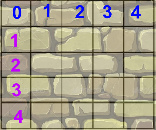
The basic idea of raycasting is as follows: the map is a 2D square grid, and each square can either be 0 (= no wall), or 1 (= wall)

You then imagine your screen as a coordinate plane, and it seperated into columns (x - axis) like so :
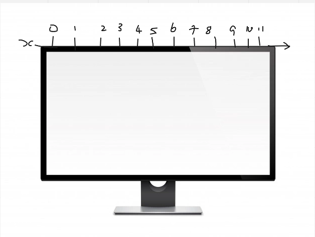
For every x of the screen (i.e. for every vertical stripe of the screen), send out a ray that starts at the player location and with a direction that depends on both the player's looking direction, and the x-coordinate of the screen. Then, let this ray move forward on the 2D map, until it hits a map square that is a wall. If it hit a wall, calculate the distance of this hit point to the player, and use this distance to calculate how high this wall has to be drawn on the screen: the further away the wall, the smaller it's on screen, and the closer, the higher it appears to be. These are all 2D calculations.
The end result will look something like this :
... and thats pretty much the basic idea of raycasting. I will be talking about map parsing and validation next, so if you want to skip to the raycasting implementation, click [here](#player-direction-vector-and-camera-vector)
## Map parsing and validating
A valid map / config file obeys the following rules:
- The map must be composed of only 6 possible characters: 0 for an empty space,
1 for a wall, and N,S,E or W for the player’s start position and spawning
orientation.
- The map must be closed/surrounded by walls
- Except for the map content, each type of element can be separated by one or more empty line(s).
- Except for the map content which always has to be the last, each type of element can be set in any order in the file.
- Except for the map, each type of information from an element can be separated
by one or more space(s).
- The map must be parsed as it looks in the file. Spaces are a valid part of the
map and are up to you to handle. You must be able to parse any kind of map,
as long as it respects the rules of the map.
These are examples of valid map files.


I wont talk much about the texture and colors here.
Unlike so_long, the rules of the map are laxed and allowing more creative freedom. The map will may not be rectangular in shape and may have many weird edges/curves and corners. However, the map can still be parsed as a 2d
character array and treated like normal strings with different lengths each row.
As such, I came up with a few map validation rules. Assume that we are scanning the map from top to bottom, left to right :
- Ignore all leading whitespaces.
- If the current row is the 0th row or the final row, only accept '1's and ' 's.
- else, The first and final character should always be a '1'.
- In the case of any non leading whitespaces, the only acceptable characters adjacent to the space are '1's or ' 's.
- If strlen(curr_row) > strlen(row_on_top) && current col > strlen(row_on_top), current character should be '1'
- If strlen(curr_row) > strlen(row_on_bottom) && current col > strlen(row_on_bottom), current character should be '1'
Those rules should pass all the map requirements given.
## Player direction vector and camera vector
Before we cast any rays, we will first have to determine WHERE to cast the rays. Obviously, we will have to define where the player is looking at.
We can do exacly that with a vector, like so.
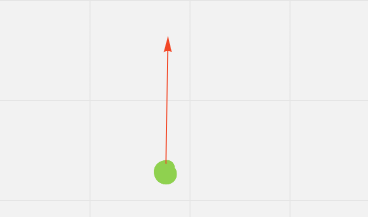
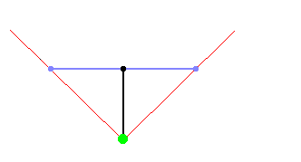
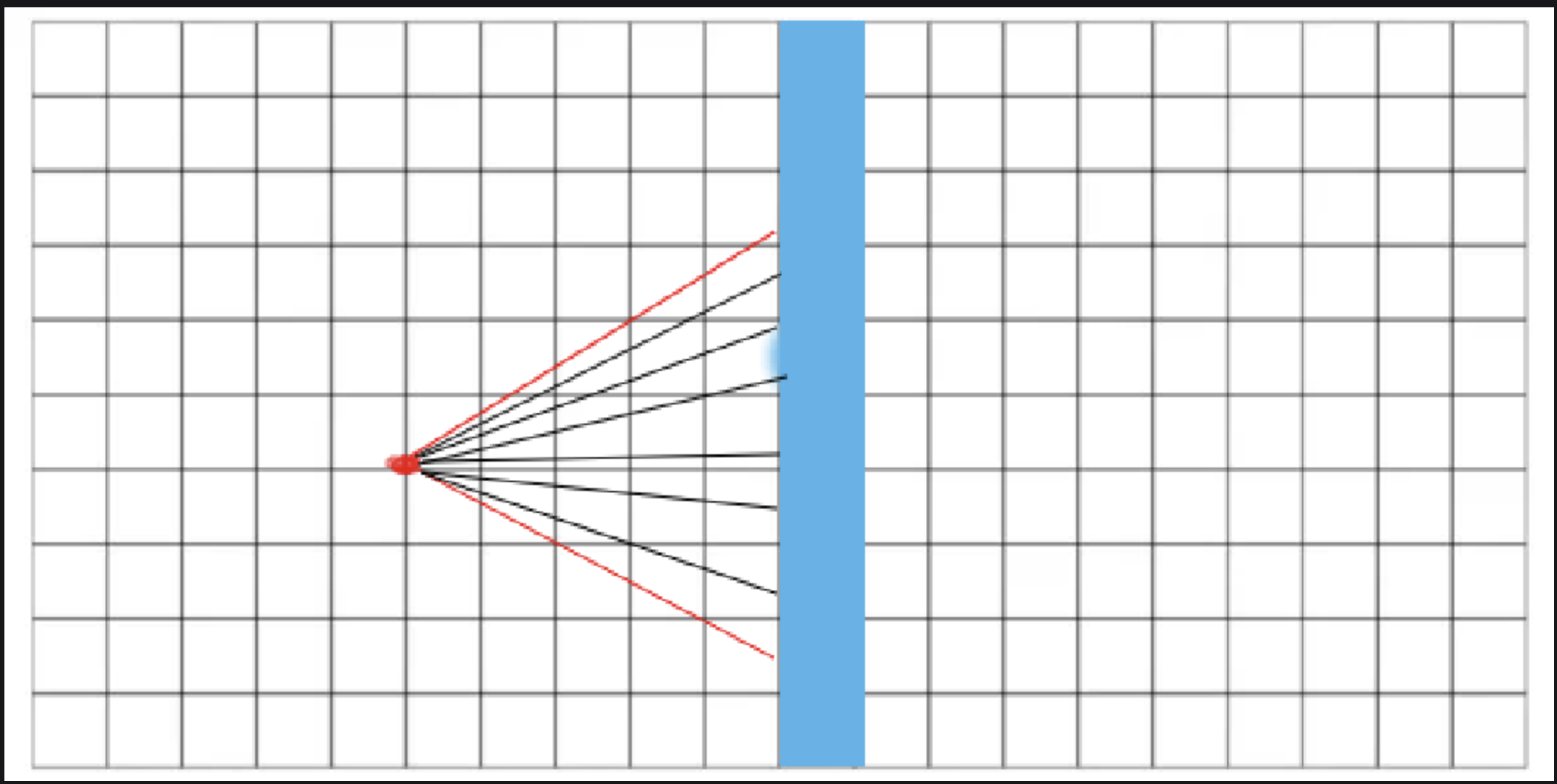
In the image above, the player (green) is looking at the north direction straight up (red line). the direction can be defined as a vector with x and y components (y = +1, x = 0).
Now we know the vector that defines the players looking direction, we can use that vector to determine the camera vector (the vector that defines FOV). The camera vector is perpendicular to the players direction vector and can be defined as so. (purple line).
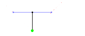
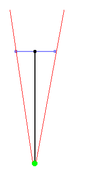
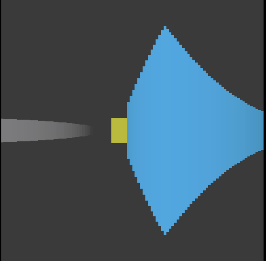
And we can connect the ends of both vectors, we will obtain a cone shaped viewing zone :
If the direction vector is much longer than the camera plane, the FOV will be much smaller than 90°, and you'll have a very narrow vision. You'll see everything more detailed though and there will be less depth, so this is the same as zooming in:
## DDA Algorithm
As mentioned in the introdution, we will have to determine the distance of each ray from the player to a wall to determine the height of the wall to draw. This brings us to an algorithm called "Digital Differential Analysis" or DDA for short.
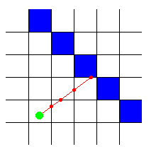
DDA is a fast algorithm typically used on square grids to find which squares a line hits (for example to draw a line on a screen, which is a grid of square pixels). So we can also use it to find which squares of the map our ray hits, and stop the algorithm once a square that is a wall is hit.
The image aboves shows how it traverses and how to stops to check if the current box is a wall or not, the image below shows the squares checked.
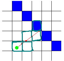
As you can see, the algorithm stops (ray stop moving forward) once one of the green boxes highlighted a wall. Since the distance between boxes are always constant (1 unit), we can just multiply the deltas between ray intersections and the map grid bounds to find the length of the ray.
## Ray Casting implementation
Below is the implementation of a simple raycaster.
First, we declare some required variables for player position and direction as
well as FOV.
```
int main(int argc, char *argv[])
{
double posX = 22, posY = 12; //x and y start position
double dirX = -1, dirY = 0; //initial direction vector
double planeX = 0, planeY = 0.66; //the 2d raycaster version of camera plane
```
After setting up the player, the gameloop starts. This should be replaced by your mlx_loop_hook function.
```
while(!done())
{
```
Here, we start the actual raycasting. We will cast a ray for every pixel of the screens width. More variables are declared.
```
for(int x = 0; x < w; x++)
{
//calculate ray position and direction
double cameraX = 2 * x / double(w) - 1; //x-coordinate in camera space
double rayDirX = dirX + planeX * cameraX;
double rayDirY = dirY + planeY * cameraX;
```
For the next section of the code, mapX and mapY represent the current square of the map the ray is in. The ray position itself is a floating point number and contains both info about in which square of the map we are, and **where** in that square we are, but mapX and mapY are only the coordinates of that square.
sideDistX and sideDistY are initially the distance the ray has to travel from its start position to the first x-side and the first y-side. Later in the code they will be incremented while steps are taken.
deltaDistX and deltaDistY are the distance the ray has to travel to go from 1 x-side to the next x-side, or from 1 y-side to the next y-side. The following image shows the initial sideDistX, sideDistY and deltaDistX and deltaDistY:
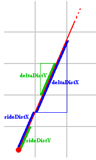
We can get deltaDistX and deltaDistY using the following formulas:
```
deltaDistX = abs(1 / rayDirX)
deltaDistY = abs(1 / rayDirY)
```
This formula is derived from pythagoras theorem, which is originally:
```
deltaDistX = sqrt(1 + (rayDirY * rayDirY) / (rayDirX * rayDirX))
deltaDistY = sqrt(1 + (rayDirX * rayDirX) / (rayDirY * rayDirY))
```
and then simplified to :
```
deltaDistX = abs(|rayDir| / rayDirX)
deltaDistY = abs(|rayDir| / rayDirY)
```
However, we can use 1 instead of |rayDir|, because only the *ratio* between deltaDistX and deltaDistY matters for the DDA code that follows later below
Finally, hit is used to determinate whether or not the coming loop may be ended, and side will contain if an x-side or a y-side of a wall was hit. If an x-side was hit, side is set to 0, if an y-side was hit, side will be 1. By x-side and y-side, I mean the lines of the grid that are the borders between two squares.
```
//which box of the map we're in
int mapX = int(posX);
int mapY = int(posY);
//length of ray from current position to next x or y-side
double sideDistX;
double sideDistY;
//length of ray from one x or y-side to next x or y-side
double deltaDistX = (rayDirX == 0) ? 1e30 : std::abs(1 / rayDirX);
double deltaDistY = (rayDirY == 0) ? 1e30 : std::abs(1 / rayDirY);
double perpWallDist;
//what direction to step in x or y-direction (either +1 or -1)
int stepX;
int stepY;
int hit = 0; //was there a wall hit?
int side; //was a NS or a EW wall hit?
```
Now, before the actual DDA can start, first stepX, stepY, and the initial sideDistX and sideDistY still have to be calculated.
```
//calculate step and initial sideDist
if (rayDirX < 0)
{
stepX = -1;
sideDistX = (posX - mapX) * deltaDistX;
}
else
{
stepX = 1;
sideDistX = (mapX + 1.0 - posX) * deltaDistX;
}
if (rayDirY < 0)
{
stepY = -1;
sideDistY = (posY - mapY) * deltaDistY;
}
else
{
stepY = 1;
sideDistY = (mapY + 1.0 - posY) * deltaDistY;
}
```
Now the actual DDA starts. It's a loop that increments the ray with 1 square every time, until a wall is hit. Each time, either it jumps a square in the x-direction (with stepX) or a square in the y-direction (with stepY), it always jumps 1 square at once. If the ray's direction would be the x-direction, the loop will only have to jump a square in the x-direction everytime, because the ray will never change its y-direction. If the ray is a bit sloped to the y-direction, then every so many jumps in the x-direction, the ray will have to jump one square in the y-direction. If the ray is exactly the y-direction, it never has to jump in the x-direction, etc..
```
//perform DDA
while (hit == 0)
{
//jump to next map square, either in x-direction, or in y-direction
if (sideDistX < sideDistY)
{
sideDistX += deltaDistX;
mapX += stepX;
side = 0;
}
else
{
sideDistY += deltaDistY;
mapY += stepY;
side = 1;
}
//Check if ray has hit a wall
if (worldMap[mapX][mapY] > 0) hit = 1;
}
```
## Camera plane vector
After the DDA is done, we have to calculate the distance of the ray to the wall, so that we can calculate how high the wall has to be drawn after this.
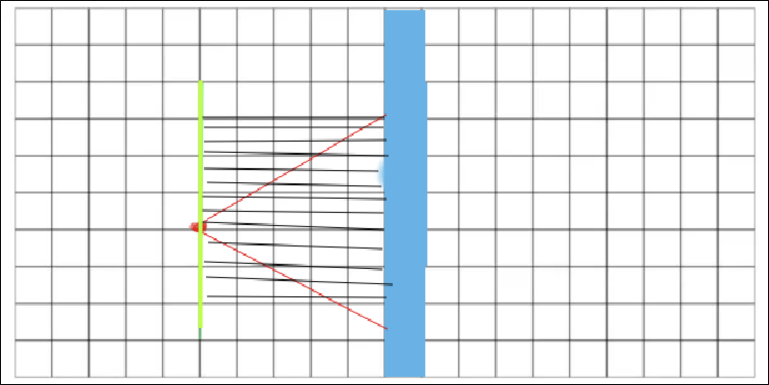
Now, the obvious points we use to calculate the dispance would be using the players position and the walls position (displayed below)
But this would result in the fish-eye effect that might not what you want it to be.
This can be fixed by using a camera place, by that we calculate the distance NOT from the player to the wall but from the plane to the wall so that the fish eye effect can
be eliminated.
Depending on whether the ray hit an X side or Y side, the formula is computed using sideDistX, or sideDistY.
Prepwalldist is the distance between the wall and the cam vector.
```
//Calculate distance projected on camera direction (Euclidean distance would give fisheye effect!)
if(side == 0) perpWallDist = (sideDistX - deltaDistX);
else perpWallDist = (sideDistY - deltaDistY);
```
## Image scaling and transformation for MLX
Now that we know the distance between the plane as the wall, we can use the information to draw images on the display using images.
Before we start drawing anything, its best that we create a struct to keep track of the line (line as in the vertical lines you draw on the display) properties.
The properties you need to keep track of are as so:
```c
typedef struct s_line
{
int x; //the x coordinate of line relative to screen
int y; //the current pixel index of the line (along y axis)
int y0; //y start index of drawing texture
int y1; //y end index of drawing texture
int tex_x; //x coordinate of texture to draw
int tex_y; //y coordinate of texture to draw
} t_line;
```
Then, you will need to create a variable that stores the position of the x-axis you hit on that wall.
For instance, if we represent the texture below as a 2d grid, you can see the x points like so:
(the x points are in blue, y in indigo)
(very bad scaled, imagine 1 grid unit is 1 pixel of the texture)
you will also need to account for the players direction because the x points will be mirrored if you player turns around.
We call this value wall_x, and we can calculate it like so:
```c
double wall_x;
if (ray->side == WEST || ray->side == EAST)
wall_x = player->pos.y + ray->prep_wall_dist * ray->ray_dir_y;
else
wall_x = player->pos.x + ray->prep_wall_dist * ray->ray_dir_x;
wall_x -= floor(wall_x); //make it start from 0
```
Now, we can set line x to the current x coord of the screen to draw:
```c
line->x = ray->curr_x;
```
After that, we can start painting the textures/colors (walls, ceiling/floor) on the screen.
```c
//paint texture if the ray hits a wall
if (root->game->map[ray->map_y][ray->map_x] == '1')
//assumes that this function paints textures
paint_texture_line(root, ray, line, wall_x);
//reset line to start at the top pixel
line->y0 = 0;
// reset line to end at the textures beginning pixel
line->y1 = ray->draw_start;
//assumes that this function paints a solid color
paint_line(root, line, root->crgb); //we paint the ceiling
//reset line to start at the bottom pixel
line->y0 = WIN_HEIGHT;
//reset line to end at the textures end pixel
line->y1 = ray->draw_end;
//assumes that this function paints a solid color
paint_line(root, line, root->frgb);//we paint the floor
```
That was a high level overview on how can you use the infromation obtained from DDA to draw something on the screen.
Before we get into drawing the textures, we have to first understand how images are formed and created in minilibx.
The image struct in minilibx contains several information:
```c
/*
** Gets the data address of the current image.
** (returned by mlx_get_data_addr)
**
** @param void *img_ptr the image instance;
** @param int *bits_per_pixel a pointer to where the bpp is written;
** @param int *size_line a pointer to where the line is written;
** @param int *endian a pointer to where the endian is written;
** @return char* the memory address of the image.
*/
```
Those in the docs werent very helpful, the real meaning behind those variables are as so:
[source](https://www.x.org/releases/X11R7.6/doc/libX11/specs/libX11/libX11.html#id2724496)
```
bits_per_pixel - The amount of bits per pixel for colouring
should be a number divisible by 3, for r, g and b
size_line - The amount of bytes for each line of the image. 0 means
the image is stored in 1 big contigious block
endian - tells you wether the pixel color in the image needs
to be stored in little endian or big endian (unused)
```
And suppose we have a function texture_on_img which will audit the image in the screen (your mlx window) with parts of the textures that you loaded (your .xpm files)
```c
void texture_on_img(
t_root *root,
t_ray *ray,
t_line *line,
t_image *texture);
```
We can change the image data by doing these calculations :
1. Calculate the scale from the screen to the texture
```c
//this value will determine how big one certain pixel
// is translated to the screen
scale = line->y - (WIN_HEIGHT) / 2 + ray->line_height ;
//since data is stored in a 1d array, we need to use the
//line_length property to get the actual offset. The formula becomes
scale = line->y * texture->line_length
- (WIN_HEIGHT * root->game->player->cam_height) * texture->line_length
/ 2 + ray->line_height * texture->line_length / 2;
```
2. Calculate the textures y coord to be printed with the scale
```c
//remember, we are printing one pixel in a straight line from top to bottom.
//this will give is the y point of the texture to print.
line->tex_y = ((scale * texture->height) / ray->line_height);
//we will need to adjust with line length so the formula becomes
line->tex_y = ((scale * texture->height) / ray->line_height)
/ texture->line_length;
```
3. Set main image data to the textures image data based on line->x and tex_y obtained
```c
// we can just simply modify the root image data
//itself with the values we obtained above
//line->y - the y point of the current vertical line
//line->x - the x point of the current vertical line
//line->tex_y - the y point of the texture
//line->tex_x - the x point of the texture
//texture->bitsperpixel - bpp/8 = r, (bpp/8) + 1 = g, (bpp/8) + 2 = b,
// Very wack need to refer to minilibx docs
root->mlx_img->data[line->y + line->x
* root->mlx_img->bits_per_pixel / 8] = texture->data[line->tex_y
+ line->tex_x * (texture->bits_per_pixel / 8)];
//and to adjust for line size
root->mlx_img->data[line->y * root->mlx_img->line_length + line->x
* root->mlx_img->bits_per_pixel / 8] = texture->data[line->tex_y
* texture->line_length + line->tex_x * (texture->bits_per_pixel / 8)];
```
To put it all together, our texture_on_img will look something like this :
```c
static void texture_on_img(
t_root *root,
t_ray *ray,
t_line *line,
t_image *texture)
{
int scale;
scale = line->y * texture->line_length
- (WIN_HEIGHT * root->game->player->cam_height) * texture->line_length
/ 2 + ray->line_height * texture->line_length / 2;
line->tex_y = ((scale * texture->height) / ray->line_height)
/ texture->line_length;
root->mlx_img->data[line->y * root->mlx_img->line_length + line->x
* root->mlx_img->bits_per_pixel / 8] = texture->data[line->tex_y
* texture->line_length + line->tex_x * (texture->bits_per_pixel / 8)];
root->mlx_img->data[line->y * root->mlx_img->line_length + line->x
* (root->mlx_img->bits_per_pixel / 8) + 1] = texture->data[line->tex_y
* texture->line_length + line->tex_x
* (texture->bits_per_pixel / 8) + 1];
root->mlx_img->data[line->y * root->mlx_img->line_length + line->x
* (root->mlx_img->bits_per_pixel / 8) + 2] = texture->data[line->tex_y
* texture->line_length + line->tex_x
* (texture->bits_per_pixel / 8) + 2];
}
```
For the walls and floors, we will just need a more simpler version of texture_on_img, since we are just printing solid colors instead of textures.
It can be implemented like so. [(Check out on how minilibx deal with colors)](https://harm-smits.github.io/42docs/libs/minilibx/colors.html)
```c
pixel_on_img(int rgb, int x, int y, t_image *img)
{
int r;
int g;
int b;
r = (rgb >> 16) & 0xFF;
g = (rgb >> 8) & 0xFF;
b = rgb & 0xFF;
img->data[y * img->line_length + x * img->bits_per_pixel / 8] = b;
img->data[y * img->line_length + x * img->bits_per_pixel / 8 + 1] = g;
img->data[y * img->line_length + x * img->bits_per_pixel / 8 + 2] = r;
}
```
Now to utilize the functions we created above, we can create our `paint_line` and `paint_texture_line` function with this steps :
1. Set the current line->y to the smaller of line->y0 and line->y1
2. Set line_max (a new var) to the bigger of line->y0 and line->y1
3. Loop through line->y to y_max
- call texture_on_img or pixel_on_img with current line.
- increment line->y
```c
void paint_line(t_root *root, t_line *line, int rgb) // or paint_texture_line
{
int y;
int y_max;
if (line->y0 < line->y1)
{
y = line->y0;
y_max = line->y1;
}
else
{
y = line->y1;
y_max = line->y0;
}
if (y >= 0)
{
while (y < y_max)
{
pixel_on_img(rgb, line->x, y, root->mlx_img);
// or texture_on_img
y++;
}
}
}
```
## Player movement and rotation
To rotate a vactor, simply multiply it with the rotation matrix
```
[ cos(a) -sin(a) ]
[ sin(a) cos(a) ]
```
(where a is the magnitude of rotation)
Since our actual direction cosists of 2 vectors (x and y), when we rotate, we need to plug the formula above to both of those vectors, in both planes (player and camera).
To move a player, we have to first check the map if the direction that we are about to move into is a wall. If not, move player according to player speed. We do the same for both x and y vectors.
```c
t_player *player;
t_game *game;
game = root->game;
player = root->game->player;
//checks for x vector
if (game->map
[(int)(player->pos.y)]
[(int)(player->pos.x + player->dir_vect.x * ceil(player->speed))]
!= '1')
//moves player in x vector direction
player->pos.x += (player->speed * player->dir_vect.x);
//checks for y vector
if (game->map
[(int)(player->pos.y + player->dir_vect.y * ceil(player->speed))]
[(int)(player->pos.x)] != '1')
//moves player in y vector direction
player->pos.y += (player->speed * player->dir_vect.y);
```
Good luck in the project!
###### tags: `graphic`