**Author:** Majid Laso
**Course:** Introdcution to applied IoT - 1DT305 at Linnaeus University
**LNU username:** ml226si
**Estimated time:** Around 20h +-10h
- [Project description](#Project-description)
- [But why?](#But-why)
- [Components](#Components)
- [How to install](#How-to-install)
- [Schematics](#Schematics)
- [Data and connectivity](#Data-and-connectivity)
- [Presenting data](#Presenting-data)
- [Final thoughts](#Final-thoughts)
- [The Code](#The-code)

The pictures show that when the garage door opens, the LED strip lights up. However, due to the bright daylight, it's a bit difficult to see the LED strip clearly.
# Project description
Did I close my garage door or not?! I don't know... Well, that's what this project aims to solve. To determine whether the garage door is open or closed with help of a micro controller unit and some other fun things. The "sensor" detects the status of the garage door and transmits the data to both Adafruit IO and makes a http request to a relay[(Shelly 1](https://www.shelly.cloud/en/products/shop/shelly-1)) located inside the house. Shelly 1 is connected to an LED strip, which illuminates when the garage door is open.
Initially, a limit switch was used to determine the open or closed position of the garage door. Later, the signals and voltages of the garage port opener were examined. It was found that the garage door opener operates at 24V and emits a 24V signal when the doors are open. To enable the D1 Mini to detect the open state, a relay was installed between the port opener and the D1 Mini. This setup allows the D1 Mini to determine whether the 24V input is high or not by opened or closed relay.
# But why?
The decision to build this specific device was based on the need to solve a practical problem: not being able to know whether the garage door is open or closed from inside the house or elsewhere. Sometimes the remote key might accidently get pressed in the pocket and you will never know if the garage door is open or not. The purpose of this project is to create a reliable way to determine the status of the garage door.... and a bit of laziness to avoid going out to check if it’s open off course.
By constructing the garage port sensor, we can collect real-time data on whether the garage door is open or closed. This data is sent to Adafruit IO, an online platform, which allows us to monitor and access the information remotely using the internet. Additionally, by connecting a relay and LED strip inside the house, we can visually see if the garage door is open or closed.
This can also be integrated in other ways, like Home Assistant or a neat looking dashboard that will visually show the door status.
# Components
| | Material | Quantity | Store | Price |
| -------------------- | :-------------------- | :------- | :--------------------------------------------------------------------------------------------------------------------------- | :-----: |
| 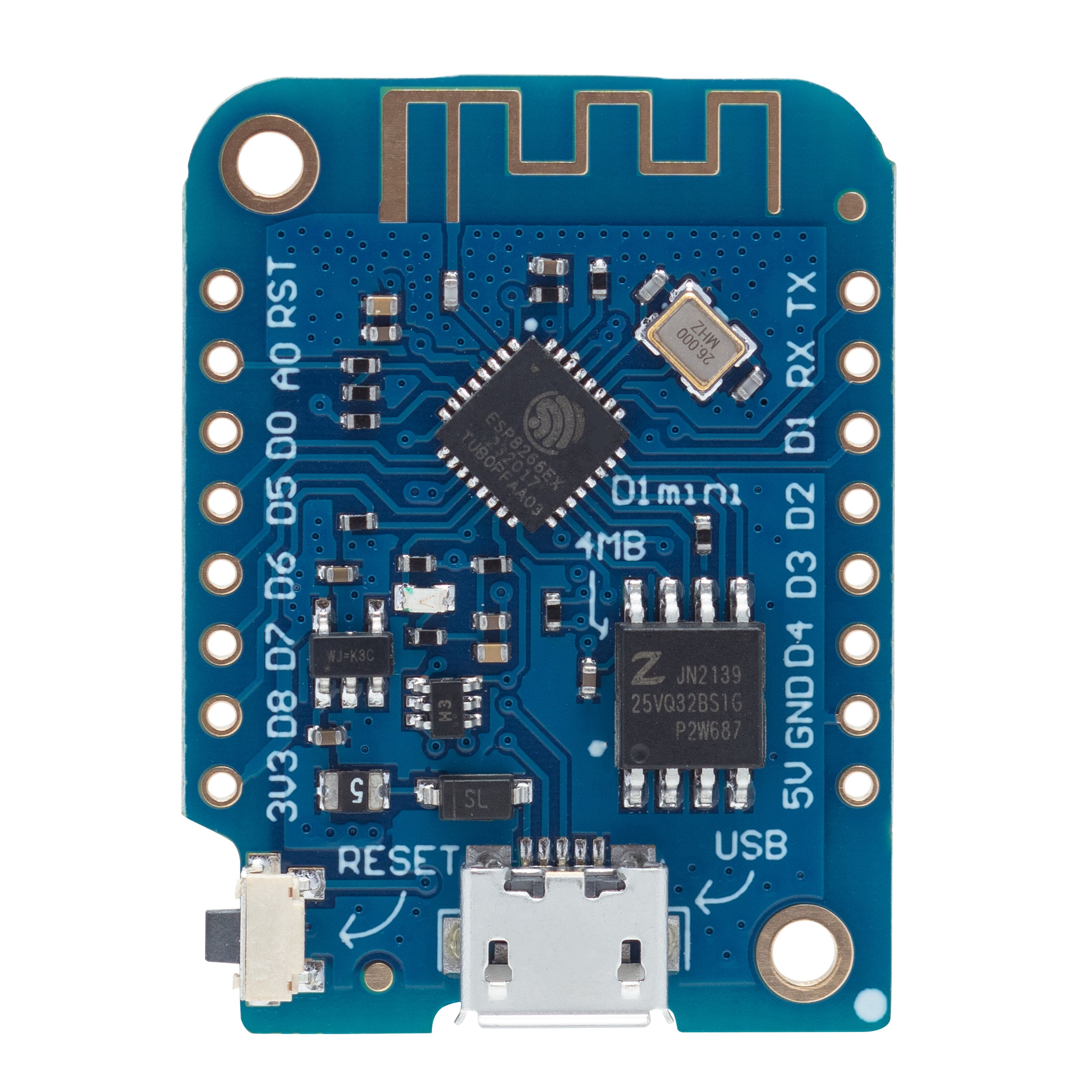 | LOLIN D1 mini | 1 | [Kjell](https://www.kjell.com/se/produkter/el-verktyg/elektronik/utvecklingskit/arduino/utvecklingskort/luxorparts-wemos-d1-mini-utvecklingskort-p87294) | 120 SEK |
| 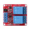 | 2ch 24V relay | 1 | [Aliexpress](https://www.aliexpress.com/item/1005005606909491.html?spm=a2g0o.productlist.main.3.68b53cf0mrVmKV&algo_pvid=35de998d-91f9-48ad-927c-6ec66efa4f9e&algo_exp_id=35de998d-91f9-48ad-927c-6ec66efa4f9e-1&pdp_npi=3%40dis%21SEK%21130.47%2187.43%21%21%2111.61%21%21%402100baf316886296242807594d0737%2112000033728728770%21sea%21SE%21167400532&curPageLogUid=eVTDcOiY8TqT) | 50 SEK |
| 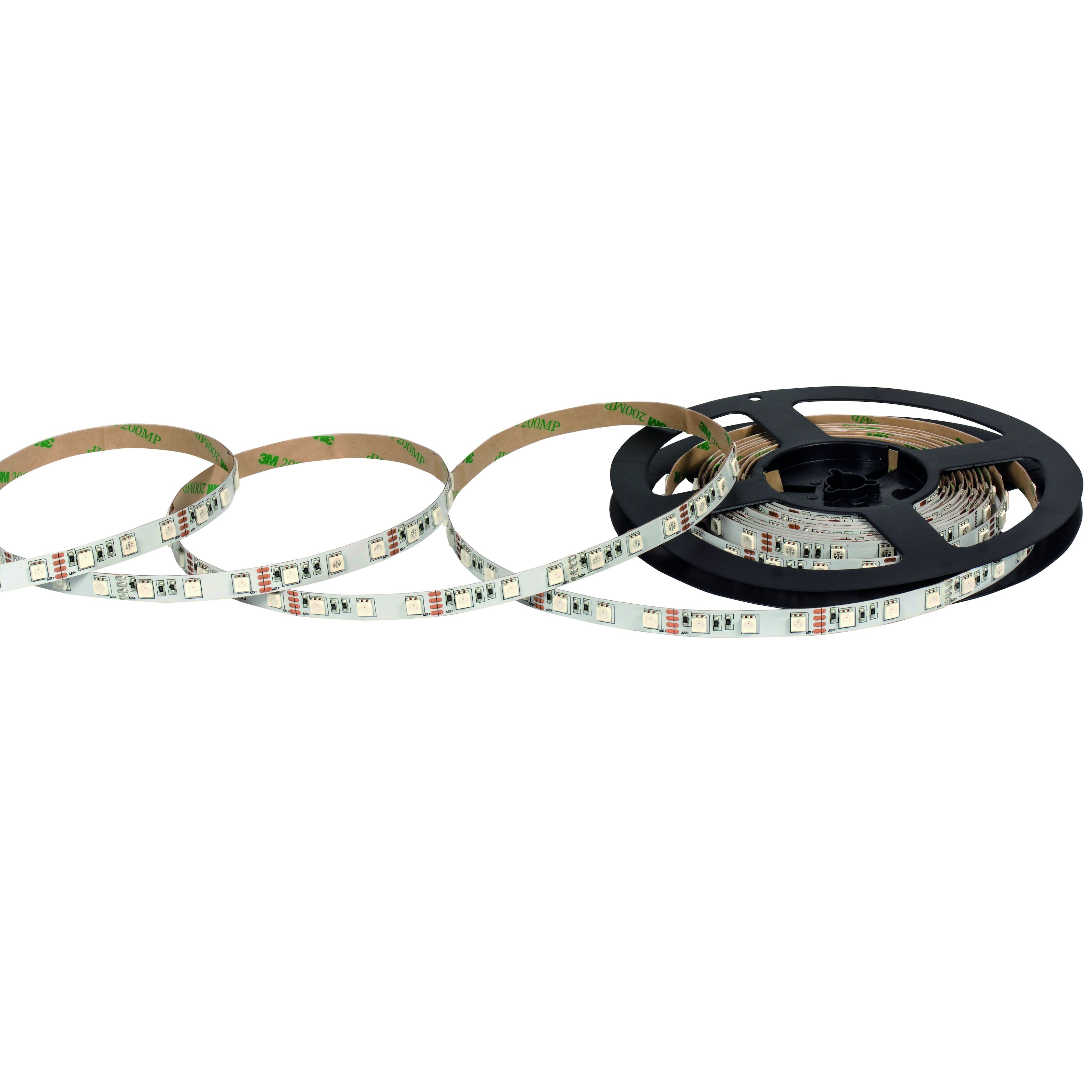 | LED Strip | 1 | [Kjell](https://www.kjell.com/se/produkter/hem-fritid/belysning-lampor/led-lister/nextec/nextec-led-list-ip33-5-m-rgb-p36340) | 599 SEK |
| 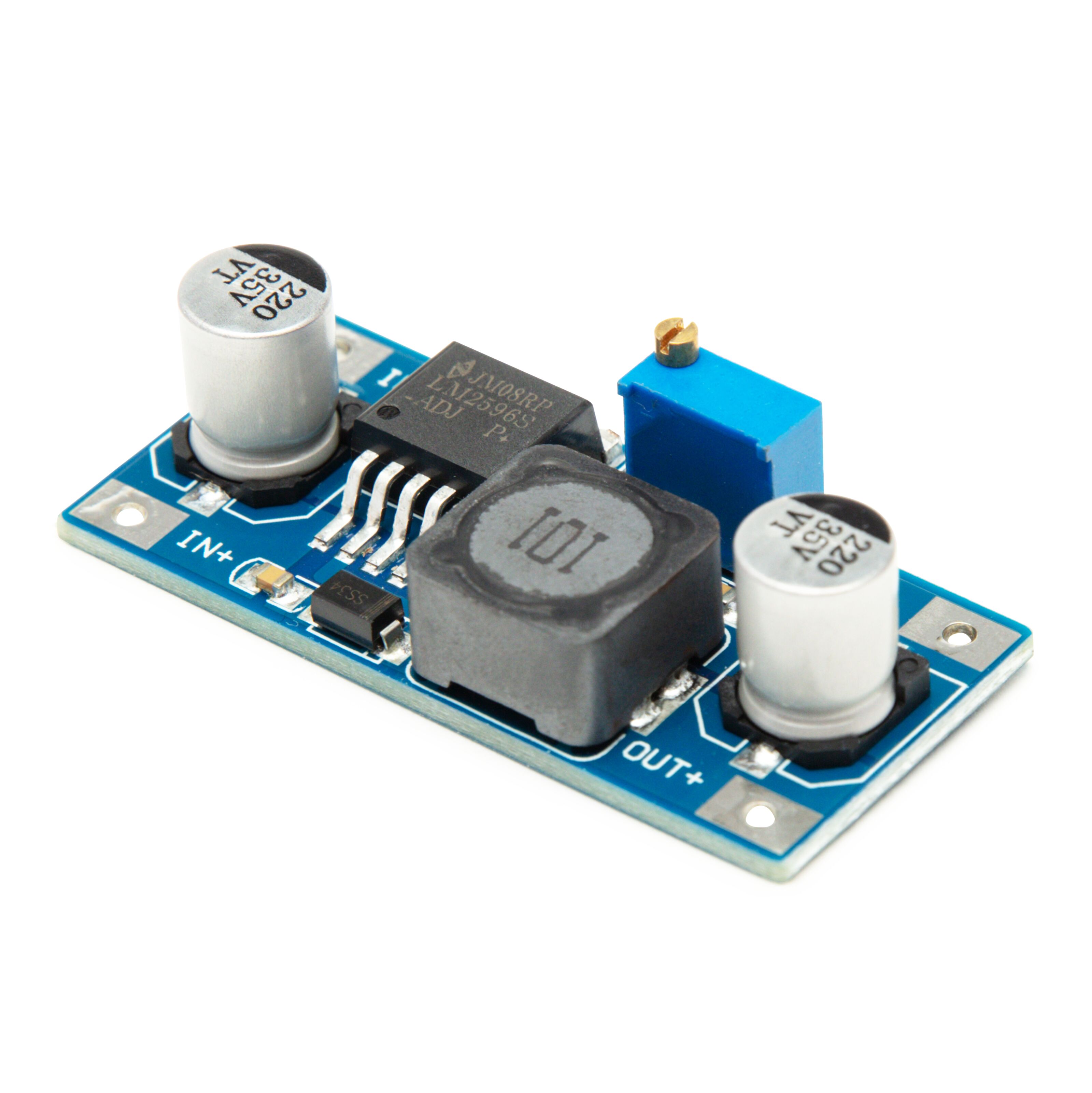 | Step Down Converter | 1 | [Kjell](https://www.kjell.com/se/produkter/el-verktyg/elektronik/utvecklingskit/arduino/stromforsorjning/luxorparts-variabel-spanningsregulator-switchad-p87049?gclid=EAIaIQobChMIpv6t0fLv_wIVDeCyCh1NRAq_EAQYAiABEgIoEPD_BwE) | 99 SEK |
| 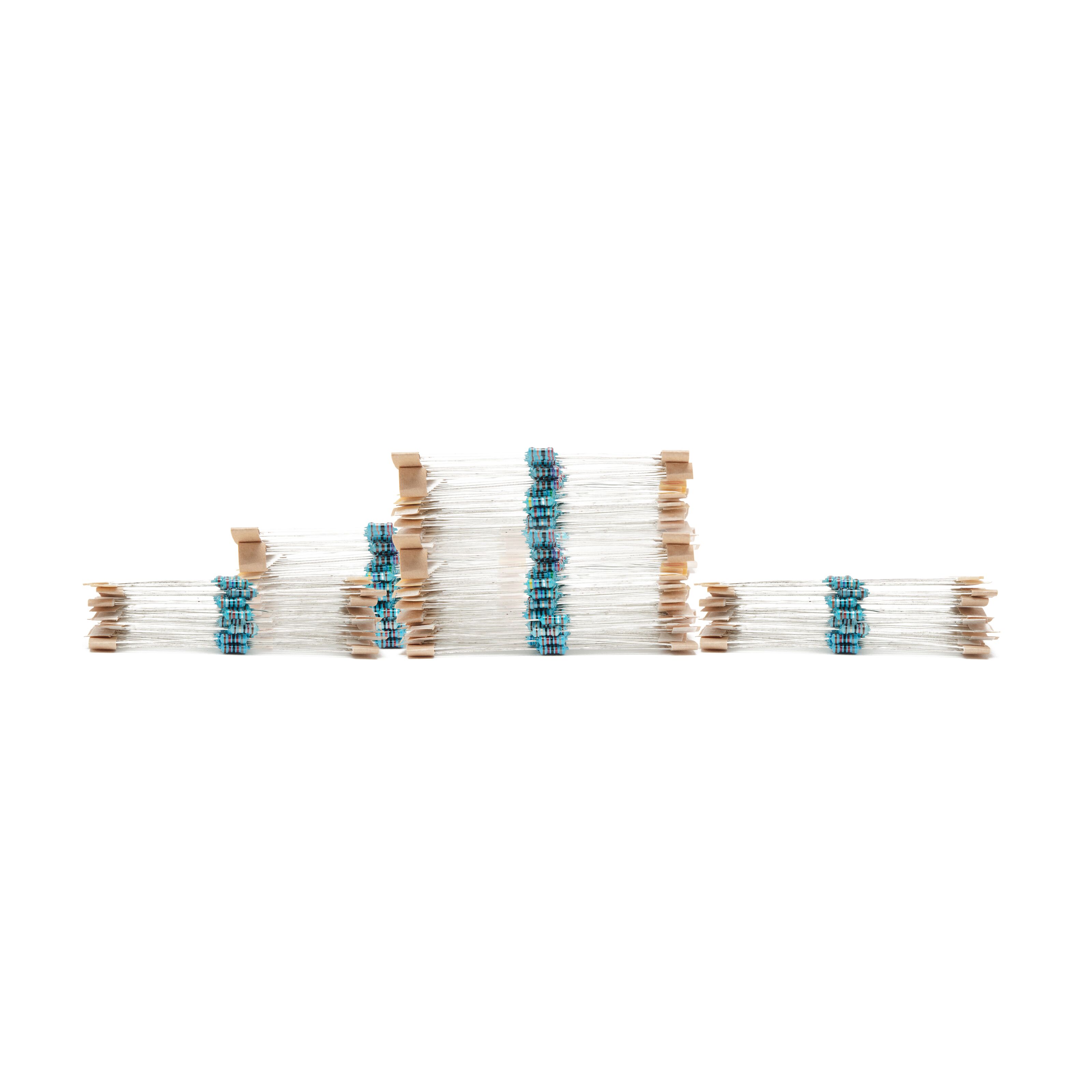 | 10k resistor | 1 | [Kjell](https://www.kjell.com/se/produkter/el-verktyg/elektronik/motstand/playknowlogy-sortiment-med-resistorer-600-pack-p90646) | 159 SEK |
| 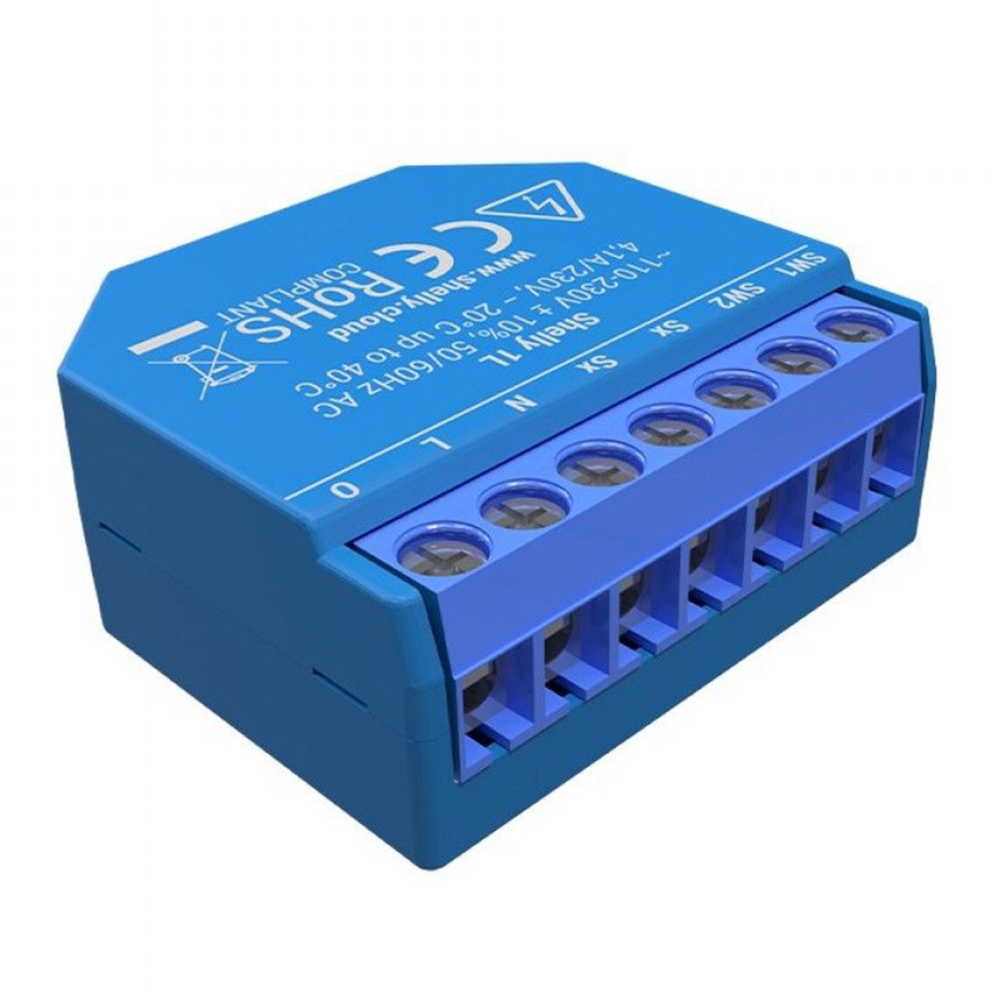 | Shelly 1 | 1 | [Kjell](https://www.kjell.com/se/produkter/smarta-hem/smarta-hem-losningar/shelly-smarta-hem/shelly-1l-infalld-fjarrstrombrytare-p52170) | 249 SEK |
| 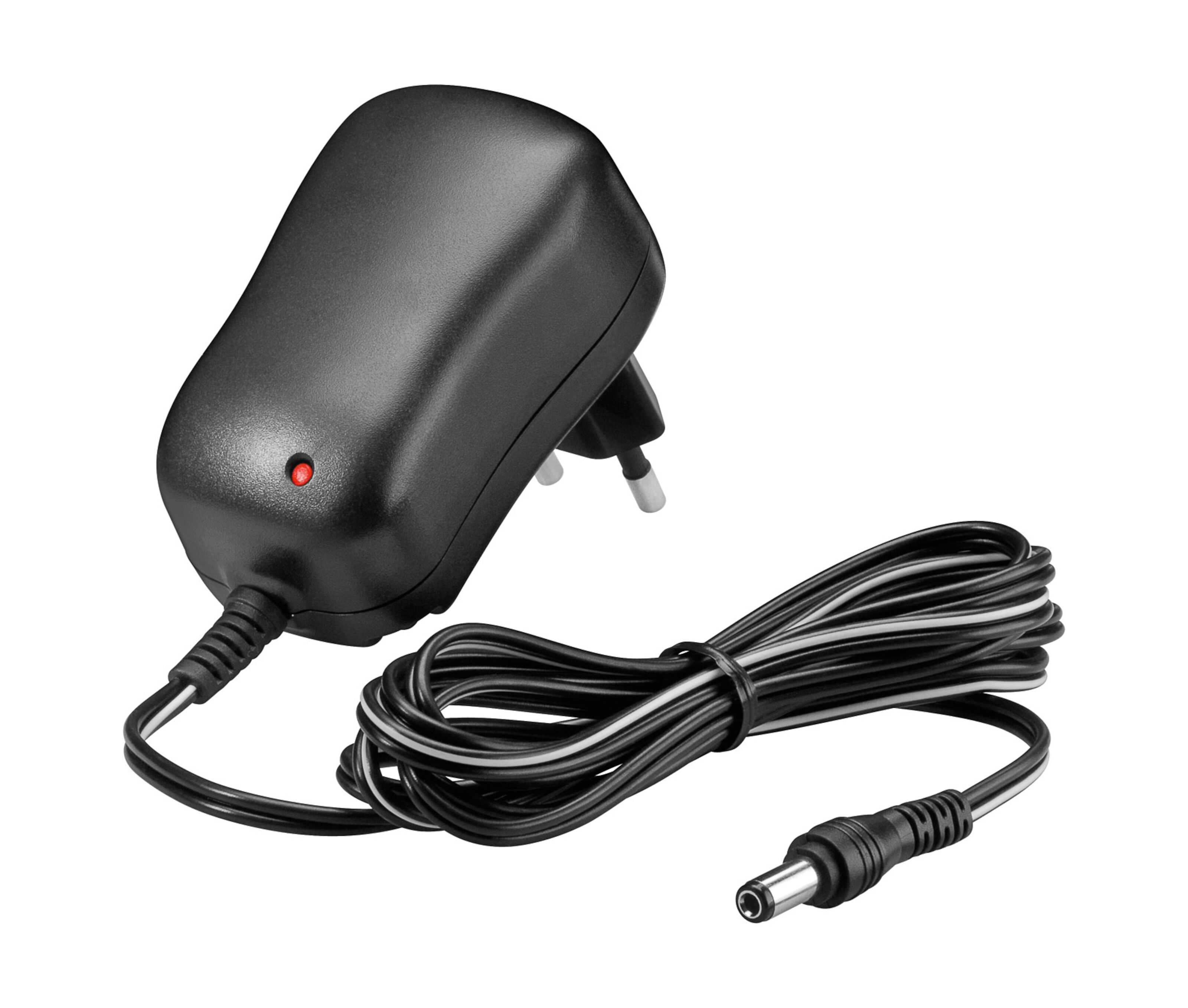 | AC/DC Adapter | 1 | [Kjell](https://www.kjell.com/se/produkter/el-verktyg/natadaptrar-nataggregat/acdc-natadaptrar/fast-utspanning/switchad-natadapter-12-v-dc-12-w-p44382) | 199 SEK |
---
1. LOLIN D1 mini: The LOLIN D1 mini is a small development board based on the ESP8266 Wi-Fi module. It is compatible with the Arduino IDE and can be used for various IoT applications.
2. The 2ch 24V relay is a module that allows you to control two higher or lower voltage devices using low voltage signals. It is commonly used in home automation projects to control lights, appliances, or other electrical devices. In this case it's used to trigger the D1 mini by closing the "circuit".
3. Buck converter/Step Down Converter: The Step-Down Converter, also known as a voltage regulator, is used to convert a higher input voltage to a lower output voltage. It is commonly used in electronics projects to provide a stable power supply for components that require a lower voltage.
4. 10k resistor: The 10k resistor is a passive electronic component that limits the flow of electric current in a circuit. It is used in various applications such as voltage dividers, current limiters, and pull-up or pull-down resistors. Needed when reading high or low voltage input.
5. Shelly 1: The Shelly 1 is a smart home device that acts as a wireless switch, allowing you to control lights, appliances, or other electrical devices remotely. This will be replaced with another D1 mini and a 2ch relay in the future when its delivered.
6. AC/DC Adapter: To power the shelly and led strip
---
# How to install
Chosen IDE: Arduino IDE
Steps for programming the devices:
1. Install Arduino IDE: Visit the official Arduino website (https://www.arduino.cc/en/software) and download the Arduino IDE suitable for your operating system. Follow the installation instructions provided for your specific OS.
2. Connect the device: Connect your device (e.g., LOLIN D1 mini) to your computer using a USB cable.
3. Install device-specific drivers: Depending on the device you're using, you may need to install specific drivers. For D1 mini [visit this site](https://www.wemos.cc/en/latest/ch340_driver.html),to download CH340 drivers.
4. Add ESP8266 board support package:
- Open the Arduino IDE and go to the "File" menu.
- Select "Preferences" to open the Preferences window.
- In the "Additional Boards Manager URLs" field, paste the following URL: `http://arduino.esp8266.com/stable/package_esp8266com_index.json`
- Click the "OK" button to close the Preferences window.
5. Select the board: Launch the Arduino IDE. From the "Tools" menu, select the appropriate board (LOLIN(WEMOS) D1 R2 & mini).
6. Select the port and set correct upload speed:
* Go back to the "Tools" menu.
* Select "Port" and choose the correct port for your device.
* Go to the "Tools" menu again.
* Select "Upload Speed" and choose "115200" from the available options.
7. Install necessary libraries: In tools then library manager, install following libraries, AdafruitIO, WiFiClient and ESP8266WiFi.
8. Write the code: Copy and paste the code that is at the bottom of this page. Remember to add a config.h file in the same folder and put in your credentials.
9. Verify, compile and upload: Click the "Verify" button (checkmark icon) to compile your code and check for any syntax errors. If there are errors, they will be displayed in the bottom console. Once your code is error-free, click the "Upload" button (arrow icon) to flash the firmware onto the device. The Arduino IDE will compile the code and transfer it to the connected device. The status will be displayed in the bottom console, indicating if the upload was successful.
10. Testing and debugging: After the code is uploaded, the device will execute the program. You can monitor the device's behaviour and use the Serial Monitor in the Arduino IDE to view debug messages, it will tell if the Wifi connected and if door is open or not.
11. Set up the shelly relay according to [this](https://www.youtube.com/watch?v=furNkY-uv1M) video and use the ip address of the shelly relay in the code.
---
# Schematics
**D1 mini wiring in the garage**
Here is a step-by-step list for wiring the D1 mini and the 2-channel relay:
1. Choose two GPIO pins on the D1 mini to use as inputs for the relay.
2. Connect a 10k resistor between each GPIO pin and the 5V pin on the D1 mini.
3. Connect the ground (GND) pin on the D1 mini to the COM1 and COM2 pins on the relay.
4. Connect one GPIO pin from the D1 mini to the NO1 pin on the relay.
5. Connect the second GPIO pin from the D1 mini to the NO2 pin on the relay.(This is if you have two garage port openers and would like to seperate them.)
6. Take the 24V DC+ and DC- from the garage port opener (Terminal 9 and 10) and connect them to the DC+ and DC- pins on the relay.
7. Connect terminal 11 on the garage door opener to the IN1 pin on the relay. If you have a second garage door opener, connect its terminal to the IN2 pin on the relay.
8. Connect the IN+ and IN- pins of the buck converter to the 24V DC+ and DC- from the garage port opener (Terminal 9 and 10).
9. Connect the OUT+ from the buck converter to the 5V pin on the D1 mini.
10. Connect the OUT- from the buck converter to the GND (ground) pin on the D1 mini.
At the bottom to the left is terminal documentation on the port opener.

**NOTE: Electrical calculations**
During the wiring process, it is crucial to consider the proper connection of the positive (+) and negative (-) terminals. Before applying power to the circuit, it is essential to double-check the connections to avoid any issues. Incorrect wiring could lead to damaging the buck converter and other components, posing a risk of failure.
When connecting the buck converter, ensure it is first linked to the power source in. Before proceeding to connect it to the MCU D1 mini, you MUST measure the output voltage and adjust it to the correct level. To do this, a digital multimeter comes in handy and is essential to avoid damaging sensitive components.
The image of the buck converter, there is a designated screw that requires careful adjustment to achieve the correct output voltage. Please refer to the marked screw for making the necessary voltage adjustments. It is crucial to execute this step with precision to ensure the buck converter operates at the desired voltage level.

Another important step is to measure the relay circuit, both in the closed and opened states, using the digital multimeter. This verification ensures that the relay functions correctly and responds appropriately to the input signals.
By following these precautions and performing thorough measurements, you can safeguard the components from potential damage and ensure a safer and successful project implementation.

Here is an image displaying the final setup. It may be difficult to see all the necessary details in the picture alone. However, the schematics provided above offer a clearer and easier-to-understand representation of the project's configuration. The schematics visually show the connections and components involved, making it easier to grasp the setup.
---
**Shelly wiring in house**

**The garage door documentation and operating instructions**


**Note:** *As you can see, the numbers on the terminals of the door opener might be different from what is mentioned in the documentation. That's why it's important to read carefully and use a multimeter to measure the signals. It is recommended to have a multimeter to ensure accurate readings.*
Most garage openers have features that will simplify this kind of project and will make it neater. By reading the garage door documentation we can see that it has terminals for both powering up the MCU and sending signal when door is open. But if this isn’t available there is always other sensor that could be easily used like reed sensors or hall effect sensors or switch relay sensor.
We can look at the picture taken from the garage door documentation and see the features. Looking at terminal 11 - 12 we can see the actual purpose. It is to connect a 24V warning light that will turn on when door is open. We use that to trigger our relay that will then trigger the D1 mini connected. And the terminal 9 - 10 are used to power up the door sensing relay and the MCU D1 mini.
---
**Platform choice**
The choice of platform was Adafruit IO. Adafruit IO is a special website that helps people connect and share information between their smart devices and the internet. It lets you collect data from your gadgets, like temperature or humidity, and see it on easy-to-understand charts. You can also set up alarms to get a message when something important happens, like if a room gets too hot. The website works with a simple system called MQTT, which helps devices talk to each other efficiently. You can also use the website with other services, making it even more useful for controlling your smart devices.
This part wasn't necessary for this project, but it's a nice additional feature to have. The platform can be combined with other IoT devices or used as a webhook to notify users when a door is open. For example, you could set up an alarm that triggers if the door is opened late at night. That's why we didn't spend too much time on the platform.
Using a local platform would be more recommended if you have a server running at home. The benefits of a local setup are that there are no subscription fees or limitations to requests. On the other hand, cloud-based solutions offer better security for open networks, and it's easier to access them from outside the local network without exposing a local machine to the public network.
The reason for choosing this platform is its secure, easy, and fast setup, which provides many benefits for this project.
# Data and connectivity
Because of the good Wi-Fi range in the garage, using Wi-Fi was an obvious decision. Wi-Fi met all the requirements and proved to be the most effective choice.
The frequency of sending data depends on how often the garage doors open or close. Every time the door opens or closes, the D1 mini sends data to Adafruit IO and a HTTP request to the Shelly 1 relay using DDD commands.
We use two protocols for this setup: MQTT for Adafruit IO and DDD commands for controlling the Shelly 1 relay and turning it on and off.
**Elaborate on the design choices regarding data transmission and wireless protocols**
Wi-Fi Data Transmission:
* Device Range: Wi-Fi offers a good range, which makes it suitable for transmitting data from the garage to the home network. If the garage is within the Wi-Fi coverage area, data transmission shouldn't be an issue.
* Security Perspective: Wi-Fi data transmission should be properly secured using encryption methods like WPA2 or WPA3 to prevent unauthorized access to the device and data. Unlike radio or lorawan that is easier to be interfered and copied.
* The design choice of sending data only when the garage doors open or close is a practical approach. It conserves energy and bandwidth by avoiding continuous data transmission.
* MQTT is designed to work efficiently over networks with varying levels of latency and unreliability. It is well-suited for remote monitoring, making it suitable for this application.
* Device Range: HTTP requests can be used over Wi-Fi within the network range, making it suitable for local communication with the Shelly 1 relay.
* Security Perspective: Security for HTTP requests is vital, especially if they are used for local communication. Implementing measures like HTTPS and proper authentication is crucial to prevent unauthorized access to the relay. This way is only recommended for local use, it can be interfered if someone sends the request in a regular browser within the local network. After a risk management, there were considered no obstacles to running the project in this way.
---
# Presenting data
**Adafruit IO Dashboard**

Showing left door closed and right door open.
The database choice wasn't given much thought due to the project's size and simplicity. Opting for a cloud-based database made sense as it offered convenience and time efficiency. While a local solution using a server running home assistant could provide more functions and unlimited requests, it would also increase complexity and time requirements, which wasn't ideal for this simple project.
Adafruit IO is an IoT platform by Adafruit Industries. It lets you connect, store, and visualize data from IoT devices. You can control devices remotely, create dashboards, and automate actions. It's user-friendly and supports various devices and sensors.Adafruit offers free services with limitations, but it fits this project perfectly. This part is the easiest part and because my word limitation I won't show in details how to setup adafruit dashboard as there are many good [tutorials by pressing here](https://learn.adafruit.com/adafruit-io-basics-dashboards/creating-a-dashboard).
***Edit from feedback:*** I've received feedback regarding the choice of the database, as explained earlier. I'm having trouble finding any reasons why it should store the data in a database, but of course, it does get stored in Adafruit IO for 30 days. We could also consider storing it in Home Assistant. But I can't find any reasons for that, and I do not recommend sending unnecessary data and exposing it if there isnt any need. So my answer to "*why not use database*" is that there isn't any need for something I wont use. But you could use database to see how often the garage door opens and closes.
Hoever there are some examples of databases to use
TimescaleDB: It is a time-series database built on PostgreSQL, designed specifically for handling time-series data commonly generated by IoT devices.
InfluxDB: Another popular time-series database that offers high performance and scalability for handling large volumes of time-stamped data.
MongoDB: A flexible and scalable NoSQL database that can handle diverse data types, making it suitable for IoT applications that deal with varied data formats.
Apache Cassandra: A highly scalable and distributed NoSQL database that provides high availability and fault tolerance, making it suitable for large-scale IoT deployments.
As for the triggers/automation, they are activated when the garage doors open or close. These events trigger requests to both the Shelly 1 relay and Adafruit IO. The Shelly 1 relay responds by controlling the LED strip, turning it on or off accordingly. On the other hand, Adafruit IO visually displays the door status online. Additionally, there is a possibility of integrating the project with other IoT devices or dashboards in the future. For instance, I’m planning to integrating it with another D1 mini and a MAX719 LED dot display to show the door status using information from Adafruit IO.
---
# Final thoughts
The project required extensive planning and careful consideration to ensure its successful execution. I made multiple attempts and explored various approaches to discover the most stable solution. However, I encountered some obstacles when not all the materials arrived on time. Nevertheless, I adapted and found alternative methods to successfully complete the project.
Though I'm still awaiting the delivery of the remaining materials, the final product is already complete and meets all our requirements. Once the rest of the materials arrive, no major changes will be necessary, as the project was designed to incorporate them seamlessly.
As for the hardware and setup, there were numerous options available, but I opted for the best and simplest approach that perfectly suited the needs.
Additional options: The doors can be conveniently managed through Adafruit IO using the current MCU D1 mini and an additional relay set. Although the doors were previously controlled by a smart IoT relay (shelly), the homeowners were dissatisfied with its security measures. However, it is entirely feasible to control the doors with the existing D1 mini without significant extra effort, as most of the setup is already in place.
Price: The total amount for this project is approximately 1000 SEK, depending on the components you choose to use. For example, instead of opting for the led strip that costs 600 SEK, you can explore alternative light sources or triggers, which could significantly reduce the overall cost.

Final product looks like this as showed before. Couldn't get any good pictures beside just bunch of wires going everywhere.
# The code
<details>
<summary>The code is here. Please click to expand/collapse code(can't be expanded in the snapshot)</summary>
```csharp!=
#include <ESP8266WiFi.h>
#include <WiFiClient.h>
#include "AdafruitIO_WiFi.h"
/************************** Configuration ***********************************/
// edit the config.h tab and enter your Adafruit IO credentials
// and any additional configuration needed for WiFi, cellular,
// or ethernet clients.
#include "config.h"
//Choose what pin you want for yourself, you might only
//need one pin or several, thats all up to you, its easy to just add anotherone
// digital pin 3 for the first button
#define BUTTON_PIN D3
// digital pin 4 for the second button
#define BUTTON_PIN_2 D4
// button states
bool current = false;
bool last = false;
// button 2 states
bool current2 = false;
bool last2 = false;
// set up the 'digital' feeds so you can see them in Adafruit io
AdafruitIO_Feed *digital = io.feed("digital");
// Feed for the second button
AdafruitIO_Feed *digital2 = io.feed("digital2");
//This is DDD commands (Direct Device to Device) for shelly.
//For example if you make a request to 192.168.1.214/relay/0?turn=on
//then relay will turn on
//Note that you will need your own ip adress to your smart relay here
const char* relayHost = "192.168.1.214";
const int relayPort = 80;
const char* relayOnPath = "/relay/0?turn=on";
const char* relayOffPath = "/relay/0?turn=off";
//Currently we are only using one relay, in future there will be two and
//thats what this code below is for.
//const char* relayOnPath2 = "/relay/1?turn=on"; // Path for the second relay
//const char* relayOffPath2 = "/relay/1?turn=off"; // Path for the second relay
void setup() {
// set button pins as inputs
pinMode(BUTTON_PIN, INPUT);
pinMode(BUTTON_PIN_2, INPUT);
// start the serial connection, this is for serial plotting so we can se whats happening
Serial.begin(115200);
// wait for serial monitor to open
while (!Serial);
// connect to WiFi and Adafruit IO
connectWiFiAndAdafruitIO();
while (io.status() < AIO_CONNECTED) {
delay(500);
Serial.print(".");
}
// we are connected
Serial.println();
Serial.println("Connected to Adafruit IO");
}
void loop() {
// io.run(); is required for all sketches.
// it should always be present at the top of your loop
// function. it keeps the client connected to
// io.adafruit.com, and processes any incoming data.
io.run();
// Check the state of the first button
bool newButtonState = digitalRead(BUTTON_PIN);
if (newButtonState != current) {
current = newButtonState;
// Save the current state to the 'digital' feed on Adafruit IO
Serial.print("sending button -> ");
Serial.println(current);
digital->save(current);
// Send HTTP request to control the first relay
sendRelayRequest(current);
}
// Check the state of the second button
bool newButtonState2 = digitalRead(BUTTON_PIN_2);
if (newButtonState2 != current2) {
current2 = newButtonState2;
// Save the current state of the second button to the 'digital2' feed on Adafruit IO
Serial.print("sending button 2 -> ");
Serial.println(current2);
digital2->save(current2);
// Send HTTP request to control the second relay
sendRelayRequest2(current2);
}
}
//We use our credentials from config.h to establish a connection to wifi
void connectWiFiAndAdafruitIO() {
WiFi.begin(WIFI_SSID, WIFI_PASS);
while (WiFi.status() != WL_CONNECTED) {
delay(1000);
Serial.println("Connecting to WiFi...");
}
Serial.println("Connected to WiFi");
io.connect();
}
void sendRelayRequest(bool state) {
const char* relayPath = state ? relayOnPath : relayOffPath;
// If 'state' is true, use 'relayOnPath'; otherwise, use 'relayOffPath'.
WiFiClient client;
// Create a WiFiClient object to handle the connection.
if (client.connect(relayHost, relayPort)) {
// Attempt to connect to the server specified by 'relayHost' and 'relayPort'.
String request = String("GET ") + relayPath + " HTTP/1.1\r\n" +
"Host: " + relayHost + "\r\n\r\n";
// Create an HTTP GET request with the appropriate 'relayPath', 'HTTP/1.1' version, and 'Host' header.
client.print(request);
// Send the request to the server.
Serial.println("Relay request sent");
// Print a message to the serial monitor indicating that the request was sent.
}
}
//If you have second relay then relayOnPath : relayOffPath should be relayOnPath2 : relayOffPath2
void sendRelayRequest2(bool state) {
const char* relayPath = state ? relayOnPath : relayOffPath;
// If 'state' is true, use 'relayOnPath2'; otherwise, use 'relayOffPath2'.
WiFiClient client;
// Create a WiFiClient object to handle the connection.
if (client.connect(relayHost, relayPort)) {
// Attempt to connect to the server specified by 'relayHost' and 'relayPort'.
String request = String("GET ") + relayPath + " HTTP/1.1\r\n" +
"Host: " + relayHost + "\r\n\r\n";
// Create an HTTP GET request with the appropriate 'relayPath', 'HTTP/1.1' version,
// and 'Host' header.
client.print(request);
// Send the request to the server.
Serial.println("Second relay request sent");
// Print a message to the serial monitor indicating that the request
// was sent for the second relay.
}
}
```
---
**Config.h file**
```csharp!=
//Config.h file
#define IO_USERNAME "Your adafruit credentials"
#define IO_KEY "The api key"
#define WIFI_SSID "Your SSID"
#define WIFI_PASS "Your WIFI Password"
#include "AdafruitIO_WiFi.h"
#if defined(USE_AIRLIFT) || defined(ADAFRUIT_METRO_M4_AIRLIFT_LITE) || \
defined(ADAFRUIT_PYPORTAL)
// Configure the pins used for the ESP32 connection
#if !defined(SPIWIFI_SS) // if the wifi definition isnt in the board variant
// Don't change the names of these #define's! they match the variant ones
#define SPIWIFI SPI
#define SPIWIFI_SS 10 // Chip select pin
#define NINA_ACK 9 // a.k.a BUSY or READY pin
#define NINA_RESETN 6 // Reset pin
#define NINA_GPIO0 -1 // Not connected
#endif
AdafruitIO_WiFi io(IO_USERNAME, IO_KEY, WIFI_SSID, WIFI_PASS, SPIWIFI_SS,
NINA_ACK, NINA_RESETN, NINA_GPIO0, &SPIWIFI);
#else
AdafruitIO_WiFi io(IO_USERNAME, IO_KEY, WIFI_SSID, WIFI_PASS);
#endif
´´´
</details>
 Sign in with Wallet


