# L293D Motor Driver

## Description:
The L293D is a quadruple high-current half-H driver. It is designed to provide bidirectional drive currents of up to 600-mA at voltages from 4.5 V to 36 V. This device is designed to drive inductive loads such as relays, solenoids, DC and bipolar stepping motors, as well as other high-current/high-voltage loads in positive supply applications.
Each output is a complete totem-pole drive circuit, with a Darlington transistor sink and a pseudo Darlington source. Drivers are enabled in pairs, with drivers 1 and 2 enabled by 1,2EN and drivers 3 and 4 enabled by 3,4EN. When an enable input is high, the associated drivers are enabled, and their outputs are active and in phase with their inputs. When the enable input is low, those drivers are disabled, and their outputs are off and in the high-impedance state. With the proper data inputs, each pair of drivers forms a full-H (or bridge) reversible drive suitable for solenoid or motor applications.
On the L293, external high-speed output clamp diodes should be used for inductive transient suppression. On the L293D, these diodes are integrated to reduce system complexity and overall system size. A VCC1 terminal, separate from VCC2, is provided for the logic inputs to minimize device power dissipation.
The L293D is characterized for operation from 0°C to 70°C.
## Applications:
Stepper Motor Drivers
DC Motor Drivers
Latching Relay Drivers
## Features:
Wide Supply-Voltage Range: 4.5 V to 36 V
Separate Input-Logic Supply
Internal ESD Protection
High-Noise-Immunity Inputs
Output Current 600 mA Per Channel
Peak Output Current 1.2 A Per Channel
Output Clamp Diodes for Inductive Transient Suppression

## Pin configuration and functions:


L293D has 16 pins which perform the following functions:
### **Power Pins**
Pin 16 (Vcc1):
5V given here
Powers the internal logic (the brain of the IC)
Pin 8 (Vcc2):
Motor supply voltage (can be 4.5V to 36V) given here
powers the motors
Pins 4, 5, 12, 13 (GND):
Connect to ground (negative terminal)
### **Enable Pins (Switch ON/OFF)**
Pin 1 (Enable 1-2):
Turns Motor 1 ON/OFF (controls outputs 1 & 2)
Pin 9 (Enable 3-4):
Turns Motor 2 ON/OFF (controls outputs 3 & 4)
👉 If enable = HIGH → motor works.
👉 If enable = LOW → motor stops (regardless of inputs).
### **Input Pins (Control signals from microcontroller)**
Pins 2 & 7 (Input 1, Input 2):
Control Motor 1
Pins 10 & 15 (Input 3, Input 4):
Control Motor 2
(can be thought of like “remote buttons” that can be pressed using Arduino/Raspberry Pi/etc.)
### **Output Pins (Connected to Motors)**
Pins 3 & 6 (Output 1, Output 2):
Connected to Motor 1 terminals
Pins 11 & 14 (Output 3, Output 4):
Connected to Motor 2 terminals
These send power to the motors according to input signals.
The figure below shows the truth table

## PWM(Pulse Width Modulation)
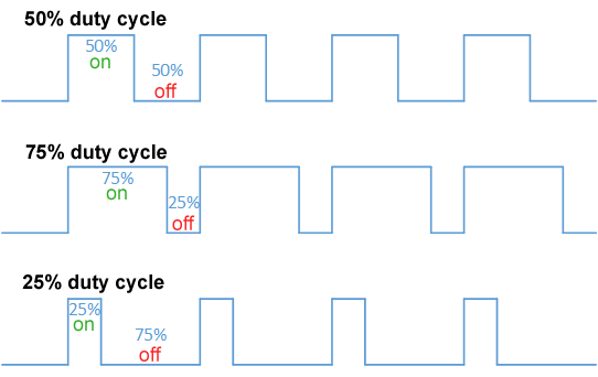
**Pulse Width Modulation (PWM)** is a technique used to control the average power delivered to a device, like a motor, by rapidly switching the supply voltage **ON and OFF** at a fixed frequency. Instead of varying the actual voltage, PWM changes the **duty cycle** (the percentage of time the signal stays ON in one cycle). A **higher duty cycle** means the motor receives more average voltage and runs faster, while a **lower duty cycle** reduces the average voltage, making the motor run slower. Because this switching happens very quickly, the motor doesn’t jerk—it simply responds as if it’s receiving a smoothly adjusted voltage, making PWM an efficient and precise method for **speed control**.
Example with a 12V motor:
100% duty cycle → Motor gets full 12V → runs full speed.
50% duty cycle → Motor gets 6V on average → runs half speed.
25% duty cycle → Motor gets 3V on average → runs slower.
So PWM lets you control speed smoothly without changing the motor’s supply voltage.
The L293D IC doesn’t generate PWM by itself — the microcontroller (like Arduino, Raspberry Pi, 8051, etc.) provides the PWM signal. The recommended way to apply the PWM to the L293D IC is by connecting the PWM signal to **Enable pin** (Pin 1 for Motor-A, Pin 9 for Motor-B).
Advantages of using PWM includes smooth speed control of DC motors, high efficiency as there is less heat loss compared to using resistor and also that it works with simple logic signals from microcontrollers.
## H-bridge
A normal transistor can only drive current one way, but a motor needs both directions.
The H-Bridge arrangement in L293D makes it possible to:
✅ Run motor forward
✅ Run motor reverse
✅ Apply braking
✅ Let motor coast
H-bridge is used to control direction of rotation of motor.
It is an electronic circuit made of four switches (transistors) arranged in the shape of the letter “H”.
It allows current to flow through the motor in both directions, so the motor can rotate forward or reverse.
If no switches are ON, the motor stops. If all are ON incorrectly, it short-circuits (which is prevented inside L293D).

The L293D has two full H-Bridge circuits (one for each motor).
Each H-Bridge is made from bipolar transistors inside the chip.
The H-Bridge connects the motor between two outputs (e.g., OUT1 and OUT2), and based on the input signals (IN1, IN2), it decides the direction of current flow.
