5/18 arduino workshop
===
[TOC]
以下是暫時的架構
# 足夠實作的知識(至少要會):
電(電荷)在導體中流動的現象,稱為電流。
導體的兩端必需有電位差。
電荷才會流動。
### 電路學基礎:
理解 電流 從 電壓大的地方 流向電壓小的地方
為什麼接線失敗會燒壞arduino針腳?
因為電流太大 導體承受不了
(電阻固定下 電壓大 則 電流大 )
(所以如果接通的電路中沒有電阻 5V出來直接接地
電壓大=>電流大=>針腳被燒壞)
電阻就是阻礙電流流動的因為 可以降低和分散電子零件的電壓 避免元件損壞
接地==0V
用水類比:
電壓 == 水位 水從水位高的地方流向水位低的地方
電流 == 水(電線裡的流水量)
電阻 == 河理的石頭
看懂電路圖裡的符號
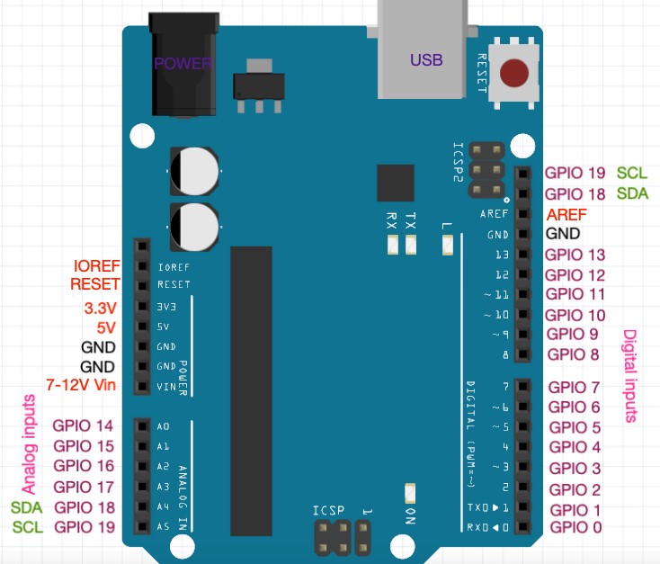
### 麵包版/跳線/電阻/arduino的pin種類(5v/gnd/類比/數位) 基礎:
-----------

-----------
---------
### arduino coding 語言基礎:
c語言也被稱為最接近低階的高階語言,代表他的語法簡潔並解能有效率的操作硬體,幾乎所有作業系統和處理器,都有C程式語言的開發工具,使的C語言成為開發嵌入式系統的首選
微處理器只認得0和1構成的指令(機械馬),我們必須把高階語言翻譯成0與1的機械碼,才能交給電腦執行。
把C語言翻譯成機械碼的過程,叫做編譯(compile),
負責編譯的軟體叫做編譯器(compiler)。
arduino板子上 每個腳位(pin) 都有它的編號
每個接腳有2個工作模式: 輸入跟輸出
void setup(){
}
void loop(){
}
pinMode(腳位編號,OUTPUT/INPUT)
digitalWrite(腳位編號,HIGH/LOW/)
delay()
程式出錯 怎麼debug
註解
變數: 資料型態(變數種類) / 變數宣告
運算子
if else
while() / for
以下可能不用教:
陣列(如果太多重複變數可能會用到)
字串(lcd會用到)
引用標頭檔(lcd要引用liquidCrystal_I2C.h)
### 實作會用到的零件 基礎:
(皆使用數位訊號)
1. led燈
2. 按鈕(還沒買齊)
3. 蜂鳴器(還沒買齊)
4. 紅外線距離感測器
5. 紅外線動作感測器
6. 溫溼度感測器
7. lcd顯示器(序列阜)
# 實作:
## 前置任務:
安裝arduinoIDE
使用 usb(micro B 轉 可接電腦的type) 將 uno板子 接上 電腦
## 作品1: led blink (example裡有)
##### 學習目標:
變數宣告
##### 電路圖:

##### Code:
int LEDpin = 2;
void setup() {
pinMode(LEDpin, OUTPUT);
digitalWrite(LEDpin, LOW);
}
void loop() {
digitalWrite(LEDpin, HIGH);
delay(500);
digitalWrite(LEDpin, LOW);
delay(500);
}
## 作品2: led 摩斯密碼
##### 學習目標:
if else
delay
##### 電路圖:
##### Code:
## 作品3: led 跑馬燈
##### 學習目標:
迴圈
陣列
##### 電路圖:

##### Code:
沒有迴圈版:

迴圈版:

陣列版:
## 作品4: 按鈕 (控制led)
##### 學習目標:
電流從高電壓流向低電壓
電流傾向於流向電阻低的線路
##### 電路圖:

##### Code:
#define LEDPin 8
//Connected to one pin of the switch
#define ButtonPin 7
// the setup function runs once when you press reset or power the board
void setup() {
// initialize LED Pin as an output.
pinMode(LEDPin, OUTPUT);
//set the Button Pin as an input
pinMode(ButtonPin, INPUT);
}
// the loop function runs over and over again forever
void loop() {
if (digitalRead(ButtonPin) == LOW) {
digitalWrite(LEDPin, HIGH); // turn the LED on (HIGH is the voltage level)
} else {
digitalWrite(LEDPin, LOW); // turn the LED off by making the voltage LOW
}
}
## 作品5: 按鈕 (控制蜂鳴器)
##### 學習目標:
蜂鳴器
##### 電路圖:

##### Code:
#define buzzer 9
//Connected to grounded resistor of switch
#define ButtonPin 7
// the setup function runs once when you press reset or power the board
void setup() {
//set the Button Pin as an input
pinMode(ButtonPin, INPUT);
}
// the loop function runs over and over again forever
void loop() {
if (digitalRead(ButtonPin) == HIGH) {
tone(buzzer, 2000); // sound the buzzer
} else {
noTone(buzzer); // turn the buzzer off
}
}
註: tone 跟 noTone function 的介紹
https://www.arduino.cc/reference/en/language/functions/advanced-io/tone/
## 作品6: 動作偵測警報器
##### 學習目標:
紅外線動作感測模組
##### 電路圖:

##### Code:

## 作品7: 紅外線距離感測器 + led/蜂鳴器 (倒車雷達)
##### 電路圖:
##### Code:
## 作品8: lcd + 溫溼度 (電路跟code求支援)
##### 前置任務:
安裝第三方套件(LiquidCrystal_I2C.h)到arduino/library資料夾裡
(mac不確定是不是這樣)
##### 電路圖:
還沒畫出來
##### Code:
#include <dht.h>
#include <Wire.h>
#include <LiquidCrystal_I2C.h>
dht DHT;
LiquidCrystal_I2C lcd(0x27,16,2); // 設定 LCD I2C 位址
#define DHT11_PIN 7
void setup(){
Serial.begin(9600);
lcd.init();
lcd.begin(16, 2); // 初始化 LCD,一行 16 的字元,共 2 行,預設開啟背光
lcd.backlight();
// lcd.noBacklight(); // 關閉背光
}
void loop(){
int chk = DHT.read11(DHT11_PIN);
Serial.print("Temperature = ");
Serial.println(DHT.temperature);
lcd.print("Temp = ");
lcd.print(DHT.temperature);
lcd.setCursor(0, 1); // new line(col, row)
Serial.print("Humidity = ");
Serial.println(DHT.humidity);
lcd.print("Humi = ");
lcd.print(DHT.humidity);
lcd.setCursor(0, 0); // new line(col, row)
delay(1110);
}
## 作品9: 手機藍芽 (使用手機藍芽控制led) (目前沒有藍芽模組)
##### 學習目標:
手機藍芽晶片模組
##### 電路圖 + code:


## 作品10: 七段顯示器 電子骰子(隨機生成1~6其中一個數)(以防進度超前 提早上完)
##### 電路圖:

------

##### Code:
int segmentPins[] = {2, 3, 4, 5, 6, 7, 8};
byte digits[10][8] = {
// a b c d e f g .
{ 1, 1, 1, 1, 1, 1, 0, 0}, // 0
{ 0, 1, 1, 0, 0, 0, 0, 0}, // 1
{ 1, 1, 0, 1, 1, 0, 1, 0}, // 2
{ 1, 1, 1, 1, 0, 0, 1, 0}, // 3
{ 0, 1, 1, 0, 0, 1, 1, 0}, // 4
{ 1, 0, 1, 1, 0, 1, 1, 0}, // 5
{ 1, 0, 1, 1, 1, 1, 1, 0}, // 6
{ 1, 1, 1, 0, 0, 0, 0, 0}, // 7
{ 1, 1, 1, 1, 1, 1, 1, 0}, // 8
{ 1, 1, 1, 1, 0, 1, 1, 0} // 9
};
byte spinDigits [6][8] = {
// a b c d e f g
{ 1, 0, 0, 0, 0, 0, 0, 0}, // a
{ 0, 1, 0, 0, 0, 0, 0, 0}, // b
{ 0, 0, 1, 0, 0, 0, 0, 0}, // c
{ 0, 0, 0, 1, 0, 0, 0, 0}, // d
{ 0, 0, 0, 0, 1, 0, 0, 0}, // e
{ 0, 0, 0, 0, 0, 1, 0, 0} // f
};
#define buttonPin 9
void setup() {
for (int i = 0; i < 8; i++) {
pinMode(segmentPins[i], OUTPUT);
digitalWrite(segmentPins[i], LOW);
}
//set up swich
pinMode(buttonPin, INPUT_PULLUP);
Serial.begin(9600);
}
void loop() {
if (digitalRead(buttonPin) == LOW) {
//roll dice
spin();
roll();
delay(500);
}
}
void roll() {
int roll = random(1, 7);
updateDisplay(roll);
}
void spin() {
for (int j = 0; j < 6; j++) {
for (int i = 0; i < 8; i++) {
digitalWrite(segmentPins[i], spinDigits[j][i]);
}
delay(250);
}
}
void updateDisplay(int value) {
setSegments(value);
}
void setSegments(int n) {
for (int i = 0; i < 8; i++) {
digitalWrite(segmentPins[i], digits[n][i]);
}
}
## 作品11(魔王): 蜂鳴器鋼琴 (按鈕按壓後 對應的蜂鳴器會發出聲音 (總共3組)
##### 學習目標:
##### 前置任務:
安裝第三方套件(Bounce2)到arduino/library資料夾裡
(mac不確定是不是這樣)
註: bounce2的連結: https://github.com/thomasfredericks/Bounce2
##### 電路圖:

##### Code:
#include <Bounce2.h>
//The +ve buzzer pin is connected to pin 9 of the Arduino
//Defining the buzzers
#define buzzer1 8
#define buzzer2 9
#define buzzer3 10
// Defining the buttons
#define button1 5
#define button2 6
#define button3 7
// Instantiate Bounce objects
Bounce debouncer1 = Bounce();
Bounce debouncer2 = Bounce();
Bounce debouncer3 = Bounce();
//Change this variable to increase number of notes to play
int noteSequence[4];
int numNotes = sizeof(noteSequence)/sizeof(int);
int currentNote = 0;
boolean challengePlayed = false;
// the setup function runs once when you press reset or power the board
void setup() {
Serial.begin(9600);
//Defining internal pullups
pinMode(button1, INPUT_PULLUP);
pinMode(button2, INPUT_PULLUP);
pinMode(button3, INPUT_PULLUP);
// After setting up the buttons, setup the Bounce instances :
debouncer1.attach(button1);
debouncer1.interval(5); // interval in ms
debouncer2.attach(button2);
debouncer2.interval(5); // interval in ms
debouncer3.attach(button3);
debouncer3.interval(5); // interval in ms
//get first sequence of notes
//generating a random number
randomSeed(analogRead(0));
generateRandomPlaySequence();
}
// the loop function runs over and over again forever
void loop() {
if (!challengePlayed) {
challengePlayed = true;
currentNote = 0;
playSequence(noteSequence);
}
// Update the Bounce instances :
debouncer1.update();
debouncer2.update();
debouncer3.update();
// Get the updated values :
int value1 = debouncer1.read();
int value2 = debouncer2.read();
int value3 = debouncer3.read();
if ( debouncer1.fell() ) {
playNote(1);
verifyNotePlayedIsCorrect(1);
}
if ( debouncer2.fell() ) {
playNote(2);
verifyNotePlayedIsCorrect(2);
}
if ( debouncer3.fell() ) {
playNote(3);
verifyNotePlayedIsCorrect(3);
}
}
void playSequence(int notes[]) {
for (int i=0; i< numNotes; i++) {
playNote(notes[i]);
}
}
void verifyNotePlayedIsCorrect(int note) {
if (currentNote < numNotes) {
if (noteSequence[currentNote] == note) {
currentNote++;
if (currentNote == numNotes) {
winner();
}
} else {
looser();
}
}
}
void playNote(int note) {
switch (note) {
case 1:
tone(buzzer1, 2000);
delay(750);
noTone(buzzer1);
delay (500);
break;
case 2:
tone(buzzer2, 4000);
delay(750);
noTone(buzzer2);
delay (500);
break;
case 3:
tone(buzzer3, 6000);
delay(750);
noTone(buzzer3);
delay (500);
break;
default:
break;
}
}
void winner() {
currentNote = 0;
challengePlayed = false;
generateRandomPlaySequence();
for (int i =0; i <3; i++) {
tone(buzzer3, 2000);
delay(250);
noTone(buzzer3);
delay(250);
}
delay(2000);
}
void looser() {
currentNote = 0;
challengePlayed = false;
tone(buzzer1, 200);
delay(1000);
noTone(buzzer1);
delay(2000);
}
void generateRandomPlaySequence() {
for (int i = 0; i < numNotes; i ++ ) {
int num = random(1, 4);
Serial.println(num);
noteSequence[i] = num;
}
}
# 補充
### 可能採用的教學格式:
根據每個作品學生實作時的狀況:
0~3分鐘:
介紹作品的邏輯跟實作方式
解釋用到的電路技巧跟coding語法
3~5分鐘:
給基礎知識跟小提示
5~10分鐘:
給電路圖 跟 code的原型
10~13分鐘:
給完整code + 助教輔助
13~15分鐘:
助教確認每組都有成功
如果還是沒做出/做失敗:
給解答 + 助教輔助做出
### 教材:
ppt 跟 ppt的下載檔
紙本講義/重要筆記
解答.md
### 沒有提到:
中斷電阻
上拉電阻
下拉電阻
歐姆定律
數位 類比
狀況:
作品太簡單:
給那個作品的進階版練習題(等其他組都做完)
學生跟不上/做不出來:
全部作品都給電路圖跟code + 助教
有困難組可能用mBlock(arduino 的 scratch)教
每個作品的電路圖跟code做成解答 放在hack.md上 限制時間到再給解答的連結 最後確定每組都有成功
(助教幫忙)
(成就感 + 越到後面越難 前面的作品一定要成功做出)
簡單的進度時間表(理想):
***5/8(六)***
- [ ] 所有作品的電路圖跟code都備齊
- [ ] 2小時的時間架構
- [ ] 教學方式確認
- [ ] 簡單分工
***5/9(日)***
- [ ] ppt跟講義 架構完成
- [ ] 先自己實作過所有作品
- [ ] 助教能夠教人
***5/15(六)***
- [ ] ppt跟講義 補齊
- [ ] 所有器材/零件/轉接線 補齊
***5/16(日)***
- [ ] 模擬一下上課
***5/18(發表日)***
 Sign in with Wallet
Connect another wallet
Sign in with Wallet
Connect another wallet