# Ultrasonic Distance Tutorial
by **Sebastian Jonsson, (sj223gb)**
This Project endeavoured to create a measurement tool by using a Pycom LoPy4 along with a HC-SR04 ultrasonic distance measurement sensor and activated by a simple PCB button. The sensordata was sent to [Adafruit](https://io.adafruit.com/) using the MQTT Protocol(Message Queuing Telemetry Transport)
This project should take no more than 16 hours to recreate.
---
## Objective
This project was chosen to create a tool that would provide a supplemental measuring tool to use for home tinkering and also because ultrasonic sensors can be entertaining with additional development in the future.
It serves the purpose of supporting my tinkering by letting me view the distance on my phone whilst logged into the Adafruit dashboard.
My hopes are that this project will open up for further tinkering on the tool itself to further refine the preciseness of its measurements and potentially open up additional modes of usage for it.
---
## Material
| Item | Purveyor | Quantity | Cost |
| ---------------------------------- | --------------- | -------- | ----------- |
| Lopy4 | Second-hand | 1 | 300 .00 sek |
| Expansion Board 3.1 | Second-hand | 1 | 100.00 sek |
| Breadboard | Second-hand | 1 | 50.00 sek |
| USB 2.0 to MicroUSB | Second-hand | 1 | 50.00 sek |
| Wires, male to male | Second-hand | 12 | free |
| Battery holder 3xAA cable JST | electro:kit | 1 | 29.00 sek |
| Battery 4xAA 1.5v lithium | kjell & company | 1 | 99.90 sek |
| HC-SR04 sensor | electro:kit | 1 | 59.00 sek |
| Soldering station | electro:kit | 1 | 199.00 sek |
| Soldering tin 1.00mm lead-free 17g | electro:kit | 1 | 35.00 sek |
| Pushbutton PCB 12x12mm - 4-pack | electro:kit | 1 | 24.00 sek |
| Resistance 1k Ohm | second-hand | 3 | free |
#### LoPy4
It is a Micropython programmable IoT platform. It acts as the brain for the things connected to it. Furthermore it can use BLE, LoRa, Sigfox, and WiFi for communication, however this project will use WiFi. The LoPy4 along with the IDE Atom which utilizes the PyMakr plugin makes development on it swift with a wide variety of sensors. An antenna can be added with ease to it for the example use of LoRa.

Fig.1. LoPy4 with headers [Pycom.io](https://pycom.io)
#### Expansion Board 3.1
It is used to connect the entire project together, making certain power and sensors can

Fig.2. Expansion Board 3.1 [https://core-electronics.com.au](https://core-electronics.com.au/pycom-expansion-board-3-1.html)
#### Breadboard
Primarily used during development in order test possible wiring options.

Fig.3. Breadboard [https://www.kjell.com/se](https://www.kjell.com/se)
#### USB 2.0 to MicroUSB
Used during development to connect to and power the LoPy4. Also used to provide updates to the software or for potential non-portable use.

Fig.4. USB 2.0 to MicroUSB [https://www.kjell.com/se](https://www.kjell.com/se)
#### Wires, male to male
The wires are used in order make certain the connections through the device can reach one another, power and sensors alike.
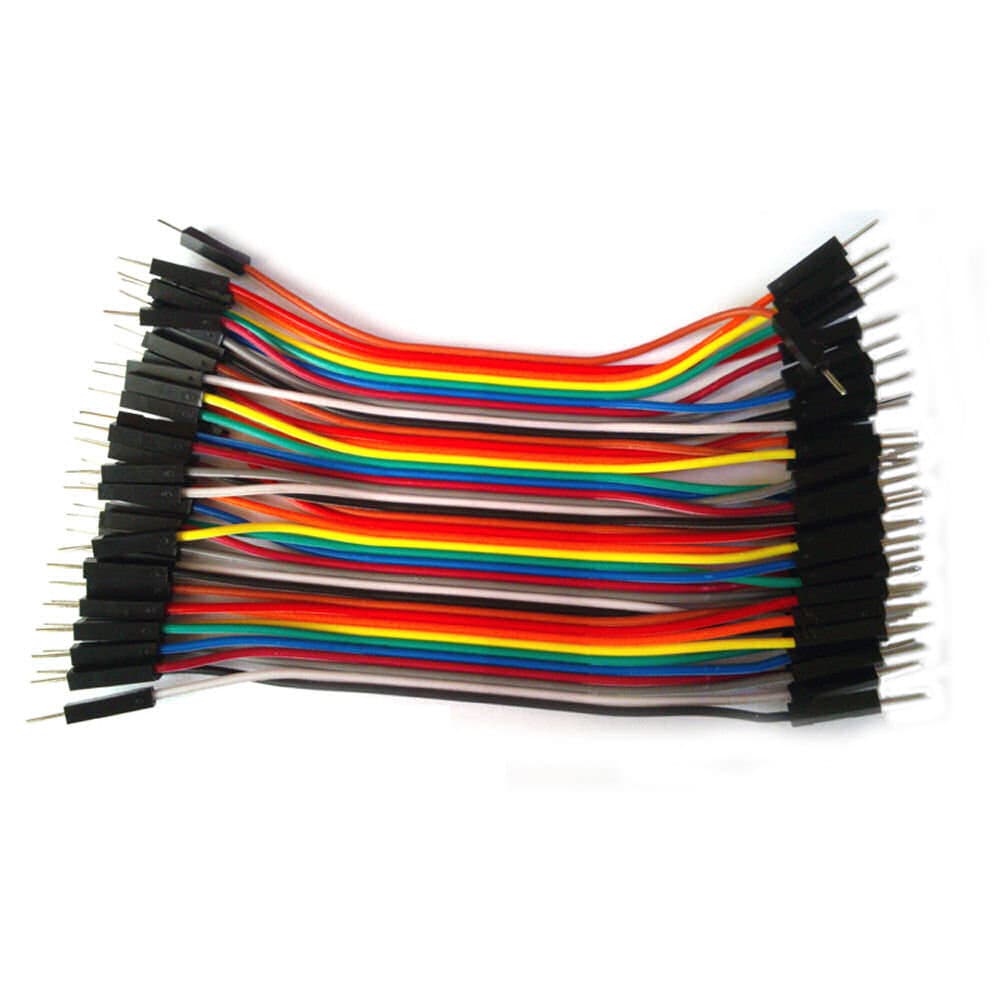
Fig.5. Wires male to male [https://www.kjell.com/se](https://www.kjell.com/se)
#### Battery holder 3xAA cable JST
A battery holder which utilizes the JST connector to the Expansion board. Enabler for portable powering of the project.

Fig.6. Battery holder for 3xAA [https://www.electrokit.com](https://www.electrokit.com)
#### Battery 3xAA 1.5V
Used to power the entire project for portable use.
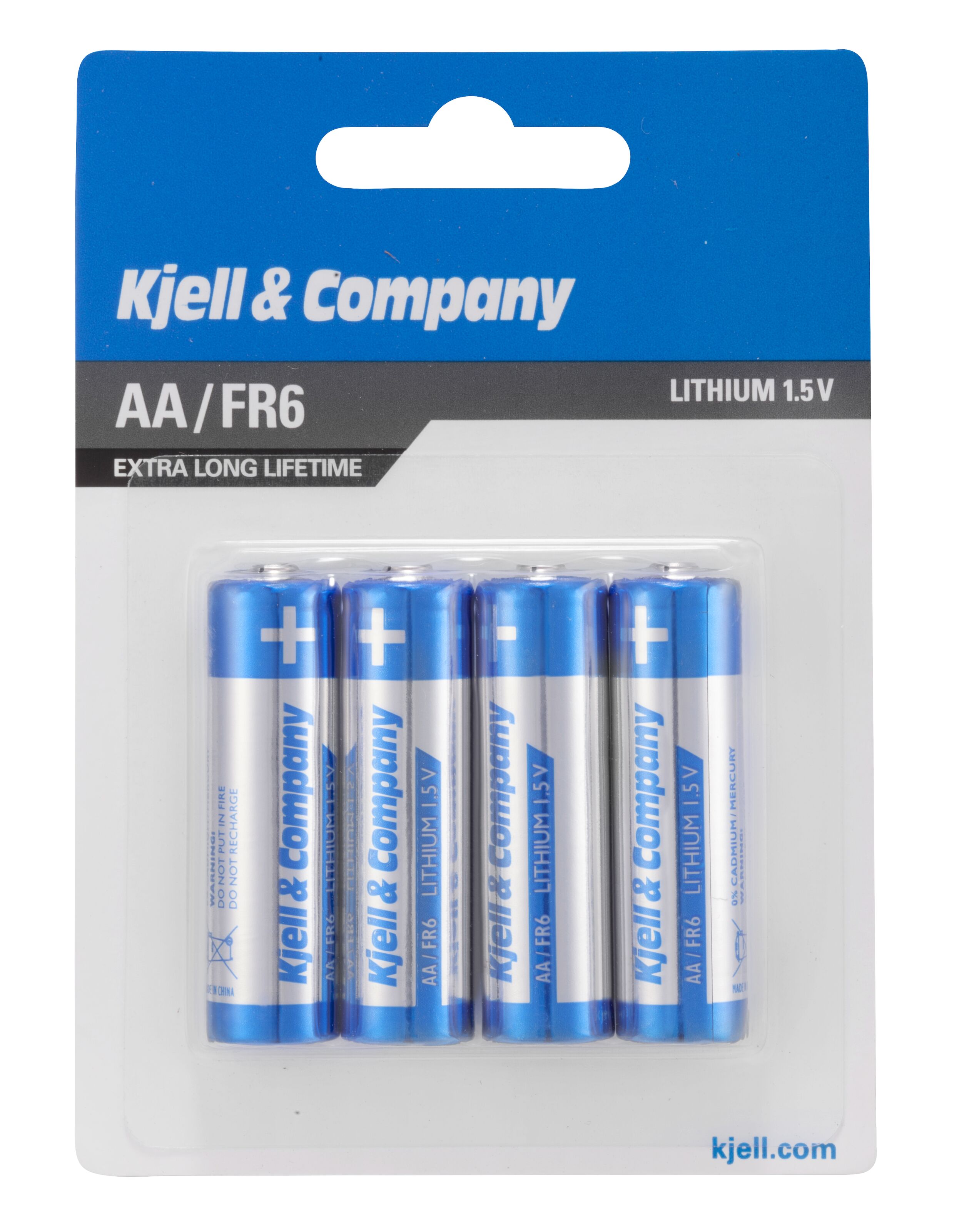
Fig.7. Battery 1.5V [https://www.kjell.com/se](https://www.kjell.com/se)
#### HC-SR04 sensor
The ultrasonic distance measurement sensor is the primary sensor we use to send ultrasonic sound and then measure the time it takes for the sound to bounce back to the receiver part of it.

Fig.8. HC-SR04 ultrasonic distance measurement sensor [https://www.electrokit.com](https://www.electrokit.com)
#### Soldering station
Used to connect the wiring properly so it does not connect loosely.

Fig.9. Soldering station [https://www.electrokit.com](https://www.electrokit.com)
#### Soldering tin 1.00mm lead-free 17g
Used by the soldering station to connect the wiring.

Fig.10. Soldering tin 1mm lead-free [https://www.electrokit.com](https://www.electrokit.com)
#### Pushbutton PCB 12x12mm - 4-pack
Used in order to activate the measurement gathering

Fig.11. Pushbuttons multicolored [https://www.electrokit.com](https://www.electrokit.com)
#### Resistance 1k Ohm
Used to create proper resistance for the HC-SR04 sensor so that measurements can be taken accurately.

Fig.12. LoPy4 with headers [https://www.electrokit.com](https://www.electrokit.com)
---
## Computer Setup
The Operating System for this project is Windows 10.
- Download and install [Atom](https://atom.io/) which became the chosen IDE for the development of this project.
- Once Atom is installed you need to add the plugin extension [PyMakr](https://atom.io/packages/pymakr) so that it is possible to connect to your LoPy4 and start adding code to the project as well as run it. This --[guide](https://docs.pycom.io/gettingstarted/software/atom/)-- will take you step by step through the process of adding PyMakr to Atom.
- Next we will update the device firmware just in case a new release has occured. Connect your expansion board 3.1 via micro-USB to your computer.
- Then follow this [guide](https://docs.pycom.io/updatefirmware/device/) where it is important that you make sure the Type/Version is pybytes. You will be required to download a tool which is mentioned in the guide in order to complete the update where you can also flash your device in the same process.
- If Python is not downloaded as part of the process of the previous steps, you should make sure you have the latest stable version of it which you can find [Here](https://www.python.org/downloads/windows/). Otherwise if you already have it, you can skip this step.
- Open Atom and create a new project, it is recomended to add a folder where you want your project to be located or you will face difficulties running it.
- Inside of the folder you just created, create another folder in it called "lib", this is where you will place the majority of your code.
- You should now be able to upload files to your device, all of which files will be explained below in the Code section.
- First however, you should download from your device so that you have access to the pybytes_config.json file, in which you want to change your wifi->ssid: to your wifi ssid and the wifi->password to your wifi password. Like the example below(Your config file will have more information in it but alter this only):
```json=
{"wifi": {"ssid": "<Your-Wifi-ssid>", "password": "<Your-Wifi-Password>"}}
```
---
## Putting everything together
I would first of all recomend reading through this [datasheet](https://cdn.sparkfun.com/datasheets/Sensors/Proximity/HCSR04.pdf) for the HC-SR04 so that you understand that you must connect the GND or the black wiring first as shown in the image below. The resistors have been added as seen in the image below mainly as a precaution, it should however be possible to run the sensor without them, however it will operate without issue according to the wiring below.
As long as the wiring is connected in this manner and you have connected the JST with battery, it should run. You could if you wanted to, add a flip-switch for the power source so that you do not need to remove the batteries after each use or it will drain the battery if you forget.

Fig.13. Circuit Diagram
---
## Platform
The development during this project started out by following some basic tutorials on how to send data across the internet. As such it utilized [pybytes](https://pybytes.pycom.io/) at first which worked very well. However it was about halfway in that it was decided that [Adafruit](https://io.adafruit.com/) could support future needs better in such as it allowed for both upload and downloading information but primarily it allowed for triggers which I connected to a Discord channel to get data directly funneled there. It was chosen because it had more support for applications in either android/ios devices or webb applications.

Fig.14. Adafruit dashboard measurement example.
---
## The Code
main.py is located above the folder lib which contains the buttons.py and ultrasonicDistance.py. Furthermore the MQTT library is put inside of the lib folder and is visually too large to be put here. Feel free to follow [this link](https://github.com/pycom/pycom-libraries/blob/master/examples/mqtt/mqtt.py) for further information about it.
Explanations of the code is inside the codeblocks below and marked with a "#" before the explanatory text.
File: main.py
```python=
import buttons
import utime
from mqtt import MQTTClient
import machine
# Credit to https://docs.pycom.io/tutorials/networkprotocols/mqtt/#app for the MQTT connection.
# sets the callback message based on topic.
def sub_cb(topic, msg):
print(msg)
# sets which client on adafruit should receive the sensordata.
client = MQTTClient("device-id", "io.adafruit.com",user="adafruit-username", password="adafruit-password", port=1883)
client.set_callback(sub_cb)
client.connect()
client.subscribe(topic="adafruit-topic")
while True:
# if the value from a button push is less than 1, we will not send any blank data to io.adafruit.
if len(buttons.shiny_Buttons()) > 2:
print (buttons.shiny_Buttons())
# determines which topic on the users adafruit account receives the data and which data is sent.
client.publish(topic="adafruit-topic", msg=buttons.shiny_Buttons())
client.check_msg()
# sleeps for a minimal time before anything else can happen, avoiding overlaps.
utime.sleep_ms(200)
else:
pass
```
File: lib/buttons.py
```python=
from machine import Pin
import ultrasonicDistance
import utime
import pycom
def shiny_Buttons():
# initialise Button pins.
blue_p_in = Pin('P16', mode = Pin.IN)
# sets the color of the button to the correct pin for sensing push.
blue = blue_p_in()
# 0 means that a button is pushed, 1 means that it is not.
if blue == 0:
bluePress = str(ultrasonicDistance.average_distance())
# returning the value from the ultrasonic distance measurement as a string.
return bluePress
else:
# else we return a string which is shorter than two.
# this is checked in main.py before sending it via MQTT to Adafruit.io.
return ""
```
File: lib/ultrasonicDistance.py
```python=
import utime
import pycom
import machine
from machine import Pin
# Credit to https://github.com/iot-lnu/applied-iot/blob/master/sensor-examples/HC-SR04%20-%20Ultrasonic%20Sensor/main.py
def distance_measure():
# initialise Ultrasonic Sensor pins.
echo = Pin('P20', mode=Pin.IN)
trigger = Pin('P19', mode=Pin.OUT)
trigger(0)
# trigger pulse LOW for 2us (just in case).
utime.sleep_us(2)
# trigger HIGH for a 10us pulse.
trigger(1)
utime.sleep_us(10)
trigger(0)
# wait for the rising edge of the echo then start timer.
while echo() == 0:
pass
start = utime.ticks_us()
# wait for end of echo pulse then stop timer.
while echo() == 1:
pass
finish = utime.ticks_us()
# pause for 20ms to prevent overlapping echos.
utime.sleep_ms(20)
# calculate the distance by using time difference between start and stop.
# speed of sound in this context being .034 divided by two for the distance to object detected.
distance = ((utime.ticks_diff(start, finish)) * .034)/2
return distance
# Runs distance_measure multiple times to get a more accurate measurement.
def average_distance():
# declares the variables to a standard value, pre-measurement.
average_distance = 0
average_list = []
# loops through the distance_measure function to gather ten values in an array.
for i in range(10):
average_list.append(distance_measure())
# calculates the average value based on the values in the average_list.
average_distance = (sum(average_list)/len(average_list))
# returns the average distance calculated for usage.
return average_distance
```
---
## Transmitting the data / connectivity
As part of [Adafruit](https://io.adafruit.com/) data can not be sent constantly with a unpaid version. However the project does not require to do a measurement and send it more than **at most 2 times every minute**, which stays within the limit Adafruit has for free accounts. As well as considering the throttle time.
As previously stated in the [Computer Setup](#Computer-Setup) the project connects to WiFi by altering the settings in the pybytes_config.json file. This is done as it is meant to be a tool for home tinkering. While WiFi is not as power efficient as LoRa since it is at home it is considered a minor issue as the battery power source will be swapped out with rechargeable ones. Furthermore the main reason being it is for home tinkering but could certainly be adopted into a LoRa setting where it becomes usable outside of the home.
Adafruit as briefly mentioned previously, utilizes a reactive trigger which sends information at once to a discord channel so that an application at this early stage in development is not required.

Fig.15. A notification from the discord bot with data from Adafruit broker.
[MQTT](https://en.wikipedia.org/wiki/MQTT) is chosen because it has a great reputation with IoT devices and because of previous experience with the protocol and the Adafruit broker. [MQTT](https://en.wikipedia.org/wiki/MQTT) - "is a lightweight, publish-subscribe network protocol that transports messages between devices." Which makes it well suited for IoT devices.
---
## Presenting the data
The dashboard holds a very simplistic view as it requires very little and shows only one type of measurement regardless. Thus see Fig.14 and Fig.15 below for the adafruit and discord views of the project.
Adafruit stores data for 30 days of each feed it has, this means in short that 30 days of measurements will be saved at any time at most. To further explain, the data is saved at most 2 times every minutes primarily because the device will not be used for taking measurements for no reason. [Adafruit's data policy](https://learn.adafruit.com/adafruit-io/data-policies) explains a little bit more how it works in depth.

Fig.14. Adafruit dashboard measurement example.

Fig.15. A notification from the discord bot with data from Adafruit broker.
---
## Finalizing the design
As I have had no access to a 3D Printer, making a proper box for the project has been difficult and thus far have only managed with failed prototypes which did not hold up to the requirements. Because of this, it is to be laid flat on the palm or wherever you wish to perform a measurement and press the button.
The intended design is to make a similar thing to the Neuralyzer of Men In Black. Where the button is placed on the bottom or backside of it while the ultrasonic HC-SR04 is on the frontside for the measurements. This would however require a different battery holder and to manually create an internal battery holder for 3AA batteries. Further it would be convenient to have a different colored button to make it blend into the design more. In order to fit the pycom and expansion board I would have had to become creative with the Neuralyzer design but nonetheless doable.

Fig.16. Neuralyzer

Fig.17. Final result of the project without a shell/box.