# Thermal Camera IoT Tutorial
###### tags: `MLX90640` `IoT` `Thermal Camera` `Micropython` `Pycom`
## Table of Contents
[ToC]
By [Simon Palm](https://www.linkedin.com/in/simon-h-palm/)
(sp223gy at Linnaeus University)
## Project overview
The final goal of this project is to create a tool for measuring the visitor count and flow during the Utnarm 2022 fair. During the process of the course, the method of this has been changed and reworked due to GDPR and data quality. The project will be using an MLX90640 to take thermal images which will in a later stage be processed to estimate the number of people in the frame. In this tutorial, only the data collection part will be covered. The project uses a Mabee MLX90640 as a sensor and is connected to a FiPy and a Pysense v2.0 X. The project utilizes Node-red to a great extent and Mongodb as a database, WiFi is used for connectivity.
### Estimated Time
>20-40 hours
## Objective
As mentioned in the overview the final goal of the project was to measure the visitor flow during the Utnarm 2022 fair. This was limited to only setting up the framework for gathering data for future model creation. This was due to time constraints and a lack of datasets for the necessary training. So the objective of the device is to:
* Measure/Take the thermal image
* Enable supervised measuring
* Create a usable dataset for further development
Supervised measuring is necessary for classifying the dataset. The thought of implementing an RGB camera next to the MLX90640 could have enabled unsupervised classification, but GDPR made this difficult.
The dataset that is created must be useful, sensor as Piezo elements were previously used but were discarded as the final model would have been GIGO (Garbage In Garbage Out). This still looms over the usage of the MLX90640 as the resolution is somewhat low (32x24) but the sensor will at maximum be mounted 4 m over its target so this will hopefully not be a problem.
The project will help me familiarize myself with microcontrollers and the many sides of IoT. It will also be one of the first times where I construct my own device to be able to measure something which will be exciting but certainly challenging.
## Material
| Item | Usage | cost | supplier | Image of item (if available) |
| ------------------------------------ | ------------------------------------------------------------------------------------------- | --------- | ----------------- | ---------|
|LNU - 1DT305 Tillämpad IoT - FiPy Basic bundle|Get going and get essentials| 1499kr | www.electrokit.se ||
|Fipy | Microcontroller, connect sensors, send & receive data |in bundle|www.electrokit.se ||
|Pysense v2.0 X| Base board (Shield)|in bundle|www.electrokit.se ||
|USB cable | Power and connect the microcontroller to the computer|in bundle|www.electrokit.se |
|Mabee MLX90640 thermal camera| Take thermal images|699kr|https://hitechchain.se/ |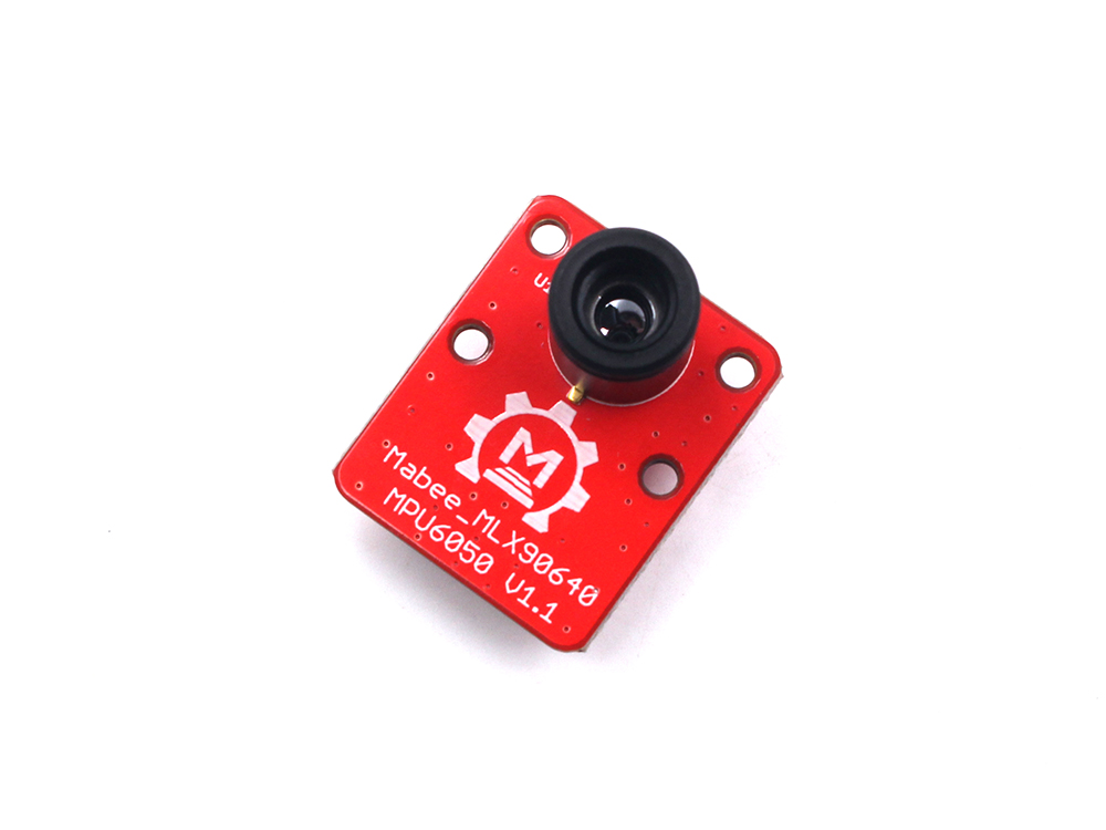|
The FiPy was good for the task as it supports different kinds of communication which could be useful in the later stages of the implementation. The Pysense is not ideal as the access to the pins is low, a board with more suitable connections would be beneficial. The MLX90640 is a good bang for the buck thermal camera. The resolution somewhat limits the project but a higher resolution is much more expensive, even lower resolution cameras are in the same price range as the MLX90640.
## Computer Setup
### IDE, Pymakr and uploading code
The IDE that I choose to use was Atom as I found that the Pymakr add-on worked better here than on VSCode. Pycom has a [guide](https://docs.pycom.io/gettingstarted/software/atom/) on how to install it on Atom. Pymakr was used to connect and upload code to the microcontroller via USB. It creates a REPL shell where you can interact with the microcontroller, with clear buttons to upload and run code. 
>Figure of Pymakr UI in Atom
### What else to download and install
To build the project Node.js needs to be installed along with [Pycoms firmware update tool](https://docs.pycom.io/updatefirmware/device/). How to update the drivers to be able to communicate with the device can be found in Pycoms [guide](https://docs.pycom.io/gettingstarted/software/drivers/). You will also need to download Python if you don't already have it.
Depending on how you choose to visualize and store the data you might need to download more things. If you follow my route you also need to install Node-red. With this you would also need to install the palettes node-red-contrib-aedes, node-red-contrib-mongodb-aleph, node-red-contrib-ui-heatmap and node-red-dashboard.
## Putting everything together

From the FiPy pin 0 and 1 are connected to the Pysense for serial communication. The Vin, GND, and 3V3 pins are connected to the Pysense. The rails are used for GND and 3.3V. The pins 22 and 21 are used for I2C to use the sensors on the Pysense, which isn't used in this project but might be a good addition. Pin 9 and 10 are connected to the MLX90640 for I2C. The MLX9640 is connected to the 3.3V rail.
This setup is for development, the MLX90640 could be connected to the port on the Pysense if the FiPy was mounted on the shield. I could not find a converter between the port type of the MLX90640 and the Pysense but the necessary pins are available on both ports which makes a connection possible. This would minimize the number of wires and make the device more compact.
## Platform
Node-red is used for visualization and as an MQTT-broker using the Aedes palette. Both Pybyte and Google IoT were tested as Pybytes was easy to set up and Google allowed Machine Learning Models which would be helpful in the final implementation of the project. Pybytes were quickly abandoned because it could not visualize the thermal image. Google IoT was hard to work with and not so beginner-friendly. Therefore I settled on Node-red as it both provided the visualization needed and was more user-friendly. It is also self-hosted which makes it more controllable and easily deployed when I was on vacation with limited connectivity.
MongoDB was used as a database, Firebase was first considered due to its Google integration but was abandoned due to authorization problems. MongoDb was also easily integrated into Node-red. I followed [this](https://www.youtube.com/watch?v=03NwekIdcMo) guide.
Because I used MQTT I also had to choose an MQTT broker. Both HiveMQ and mosquitto were tried but were abandoned due to outdated or complicated tutorials. Therefore the Aedes broker in Node-red was used as this was easily integrated into Node-red as a palette.
## Code
The sensor library was taken from [github](https://github.com/avsg8/MLX90640_micropython). There was also example code there that was used for the structuring of the thermal image vector.
As the mqtt library I used Pycoms own with some slight modifications, I added a new property to the MQTT client class which I used as a toggle in conjunction with the callback function. This made it possible to sunscribe to a topic in the dashboard and only send data when needed.
``` Python=
client.subscribe('Counted', qos = 1)
if client.send:
client.publish('Frame', str(frame), qos = 1)
client.publish('Ambient', str(amb), qos = 1)
client.publish('Time',str(time.gmtime()), qos = 1)
```
This was used to not clutter the database with bad data, so this is to supervise the quality of the data collection and will be changed when the model creation is done.
For connecting to the WiFi the [guide and code](https://hackmd.io/@lnu-iot/SJ8TGsUd5) given in the course was followed.
A large part of the programming was done in Node-red. Because NOde-red also handled the MQTT brokerage.

In the function nodes Node-red's [guide](https://nodered.org/docs/user-guide/writing-functions) on functions was used with global instead of local context, to create a global counter for usage in the database as _id.
The code is very adhoc, and many parts of it could be redone better especially the libraries. My implementation can be a starting point but should be improved upon. Here is my main.py.
``` Python=
"""
`adafruit_mlx90640` micropython example code
================================================================================
* Author(s): Avishek Guha (avsg8, @avs_g8)
Adapted by Simon Palm (SimonHPalm)
"""
import pycom, machine, micropython, time
from mqtt import MQTTClient
from machine import I2C
import busio
import adafruit_mlx90640
from network import *
rtc=machine.RTC()
rtc.ntp_sync("pool.ntp.org") #To update time
pycom.heartbeat(False) #switch off heartbeat
broker_addr = Current.address
client = MQTTClient("PMtesting", broker_addr, 1883, "SimonHPalm", "Password")
if not client.connect():
print ("Connected to broker: "+broker_addr)
def sub_cb(self, topic, msg): #the action you want to happen, when you receive a msg
self.send = True
client.set_callback(sub_cb)
time.sleep(2.0)
while True:
client.send = False
pycom.rgbled(0x0000ff) #inidicates start of code block by red led
try:
pycom.rgbled(0x0000ff) #inidicates start of code block by red led
ixc = busio.I2C(pins=('P9','P10'), frequency=400000) # read on some forum that 400KHz is the highest baudrate that
# wipy can support reliably
mlx = adafruit_mlx90640.MLX90640(ixc)
mlx.refresh_rate = adafruit_mlx90640.RefreshRate.REFRESH_0_5_HZ # 2Hz or higher refresh rates produce 0s for alternate pixels,
# like a checkerboard pattern; maybe the microcontroller cannot
# read as fast?
frame = [0]*768
mlx.getFrame(frame)
mn = round(min(frame),1) # minimum temp in the frame, rounded to 1 decimals
mx = round(max(frame),1) # maximum temp in the frame, rounded to 1 decimals
"""To get ambient temperature of the board see adafruit_mlx90640's implementation of the method for further clarity.
I just copied that over here."""
amb = [0]*834
mlx._GetFrameData(amb)
amb = mlx._GetTa(amb) - 8.0 # this is ambient temp in Centigrade
amb = round(amb,1) # ambient temp in C, rounded to 1 decimal
pycom.rgbled(0x00ff00) # inidicates successful execution of code
ixc.deinit()
client.subscribe('Counted', qos = 1)
if client.send:
client.publish('Frame', str(frame), qos = 1)
client.publish('Ambient', str(amb), qos = 1)
client.publish('Time',str(time.gmtime()), qos = 1)
except Exception as e:
print(e)
pycom.rgbled(0xff0000) # indicates some error occured
```
It will probably quite soon be on Github but I don't want to upload it in its current state.
## Connectivity and Transmitting data
Both LoRa and LTE were considered as connectivity options, I did not have LoRa coverage in the place where I mostly did the project development which made it not possible to use. LTE would have been the preferred option but due to problems activating the SIM card it could not be used. Therefore I used WiFi as I had coverage and made it possible to skip the firewall problems with local hosting. I first wanted to use the FiPy in promiscuous mode to trigger the data collection. But as the WiFi was used for the main connectivity some problems would occur due to there being no filtering of packets as MAC addresses are covered under GDPR.
The data is sent when an observer chooses. The Counted topic in the MQTT broker toggle when the device sends data. Therefore the MQTT protocol is used as previously mentioned. HTTP was used for sending the data to MongoDB. This was done from Node-red so did not impact the device itself.
## Presenting the data
Node-red was used for this, the dashboard does not look that pleasing but it gets the job done. 
The ambient temperature is calculated from the MLX90640 and is used to compare the sensor data to other sensor data. The time is used for cataloging when the measurement is taken. The number of people form is the driver of the flow, entering a number and pressing the enter button is what causes the device to send data and the dashboard to update. The heatmap is created with the array that the MLX90640 returns and is created with the heatmap node.
## Finalizing the design
All and all I am pretty happy with the result. I have tried many things for every step of project development. But the true testing part of the sensor has not been done. The fear of a GIGO system is still looming, image quality is very bad, and one can almost not identify a person in the image. Hopefully, that is mostly due to the very hot weather that we are having in Sweden right now.
 The device itself does not look that good, in lack of a male port for the MLX90640 I just used jump cables which is not that nice. A 3D printed case would have preferable both for camera stability and appearance. It takes quite a while for the MLX90640 to adjust to a new viewing angle which makes it hard to take good images when holding it by hand.
But it still gave some cool results for example this image of my hand. 
So I think that the project is a success, it can be improved both in terms of software and hardware but in the end, I think that it is able to do what I need it to do.
The project has been quite stressful, from late deliveries to GDPR stopping almost all of my project ideas, problems with programs, and almost bricking the device (a few times). It has been really stressful but a real learning experience. At least I now have predator vision.