# CAN
###### tags: `firmware_hardware` `electrical_system` `NTURT`
WIP :hammer_and_wrench:
- [CAN on STM32 Cube](https://hackmd.io/eypnzflRStm2jrNS-REpvg)
Before we start, please note that the CAN standard defines several different types of CAN, but here we will discuss only the more popular high speed CAN. Low speed CAN also exists but its configuration is a bit different there, so please note that we will discuss everything coming up based on high speed CAN.
## Physical Standards
In this section we dicuss how each bit is sent on the bus.
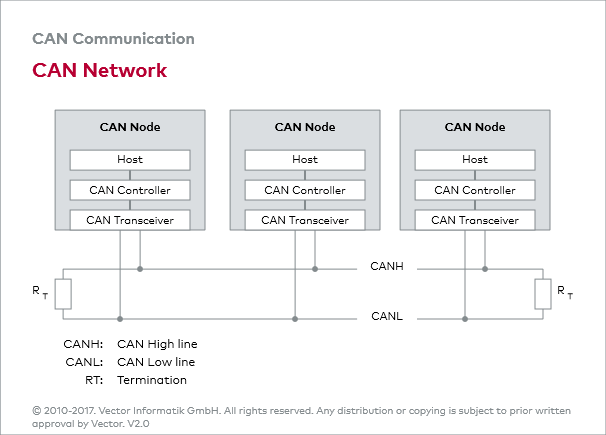
As shown above, a physical CAN network is made up of a main bus and serveral "nodes" connected on the bus.
### Bit Representation
Typically, a CAN bus is just 2 seperate wires twisted together. These 2 wires are called CANH and CANL. unlike Tx and Rx on serial connections, or SCL and SDA on I<sup>2</sup>C, CANH and CANL together represents only 1 bit on the bus. This is because CAN detects logic level by the voltage difference of the 2 wires instead of the absolute voltage on the wire.

If there is a voltage difference on the 2 wires, it is considered a logical 0. If the 2 wires have no potential difference, it is considered a 1.
Because there can be multiple nodes on the same bus, it is almost guaranteed that 2 nodes would try to drive the 2 wires to different bits. CAN incorporates a special physical feature that make it so that when 2 different nodes drives the bus to different voltage potentials, the bus is not shorted. If 1 node wants to drive the bus to a 1 and the other wants to send a 0, the bus is always drove to 0. So, 0 is also called a dominant bit, and 1 is a recessive bit.
### Node
A node is a physical unit that can independently send CAN messages. Typically, a CAN node should be consist of a CAN controller and a CAN tranceiver.
A CAN controller is a piece of hardware that should implement the logical rules the CAN protocol defines. It would read the application requirements, and then converts the data into CAN packets for transmission. The CAN controller would then send the bitstream it want to send to a CAN transceiver. On STM32s, this is usually achieved by a peripheral called bxCAN of CANFD.
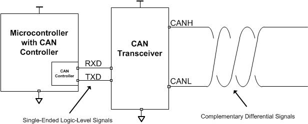
CAN controllers usually output bitstream as logical high and low voltages, while the CAN bus requires that a node transmit data as a differential signal through CANH and CANL. So, what a tranceiver does is that it bridges logic voltages and differential signals.
Sometimes it is required for CAN to transmit signals between galvanically isolated systems. For example, BMS and inverters would want to talk to the VCU on an EV car. Some CAN tranceivers can act as the isolation barrier for the CAN bus. In such case, Gnd for the Tx side and the Gnd on the CANH side would be different. This isolation is not a requirement, so be sure to check your paticular component's datasheet.
### Wiring Topology
The physical CAN bus is said to have a "main trunk" and many "small branches".
To be continued...
### Grounding
Grounding is a bit complicated here, and I must admit that I do not fully understand how Gnd works in CAN. Here I will try to lay out the things I know, and please regard this part as a personal note and view it with a grain of salt. Please feel free to google stuff about CAN ground, ground loops, and isolation yourself.
------------------------
CAN is a differential signal, so the absolute voltage on CANH and CANL doesn't effect the transmitted signal in theory. However, CAN transceivers can't withstand infinite common mode voltage on the pins in a real world scenario. Typically, the voltages on CANH and CANL should be 2.5 +- 1V as defined in the CAN standard, but CAN tranceivers usually have their own maximum allowed voltage written in the datasheet. This raises 2 questions.
1. What is the reference voltage potential this 2.5+-1 V is measured against?
2. Why would there be a Gnd shift on a bus if all tranceivers are in spec?
CAN tranceivers each have their own Gnd pin, and 2.5V would be measured against this pin. However, we can't guarantee that each node on the same bus have the same ground potential since there may be galvanically isolated systems. Ground shift and EM waves can mess up our ground as well.
----------------------------
Another role Gnd plays in CAN systems is shielding. Twisted pair of wires is good for resisting EMI, but shielded twisted pair of wires is better for resisting EMI. For environments like cars that a whole bunch of EM wave radiating components in a small packge, thowing a Gnd shield around long signal wires is probably a good idea.
--------------------------------
Ground loops can be a concern for CAN buses with a ground connection, as with many other transmission protocol. Ground loop happens when 2 devices connect their Gnd together via 2 different path by, for example, a power line and a siganl ground. This can create a loop of conductor, which is prone to picking up EM wave that can mess up our day.
To be Continued...
### Bit Timing
Although CAN requires each node on the bus to agree on a fixed baud, clock speed mismatch between nodes is inevitable. So, CAN protocol defines a method for each node to dynamically adjust the length of a bit when the node detects a mismatch between its clock and the received signal's timing. To do this, 2 things happen in a node's internal timing mechanism:
1. A bit on the bus is chopped into 4 parts, and each node should set the length of these 4 parts instead of directly setting the bit interval or baud.
2. Instead of a bit interval, the smallest unit of time in a CAN controller's internal timer is a "time quantum". Time quanta are used to calculate how long are the 3 segments of a bit metioned above.
Note that a CAN controller can freely and independtly set the above bit segment lengths as long as the sum of all bit segment lengths equals the recipricoal of baud of the bus.
<div align="center">
<img src="https://www.kvaser.com/wp-content/uploads/2014/01/bit-timing-1.gif" />
</div>
to be continued...
## Logical Protocol
We this section we dicuss how the bits on the CAN bus are put together.
### Frame
When we humans write mails, we usually follow a common "mail structure" with greeting, body, closing, etc. Similiarly, CAN requires all nodes on the network to speak in a definite format to keep order since there are no central master to control the whole network. According to the CAN standard, when a node on a CAN bus wants to talk, it should not send its content as barebone bits or words, but as "frames" with a predefined structure. A typical frames looks like this:

A frame can be broken down into several fields, each with their dedicated functionality:
1. Arbitration field is the first part of a frame, right after "start of frame" bit. This field act as the "title" or "envelope" of the frame. The ID of the frame and the type of the frame should be written here, and receiving nodes should use these information to determine what data to expect.
2. Control field is the field that indicates how many bytes the CAN frame contains. A normal CAN frame can contain 1 to 8 bytes of data at a time.
3. Data field is just the data to be sent. applications can determine the content freely.
4. CRC is a method that
5. after CRC, an bit is left 1 by the transmitter. This bit is reserved for the receiver to acknowledge that the frame is correctly received. if all goes well, the receiver should override the bit with a 0 to show the transmitter that no error has occured. This bit is known as the ACK bit.
6. After everything is done, a segment of 7 recessive '1' bits is left at the end of frame(EOF).
In practice, what we mostly have to take care of ourselves is the arbitration field(the envelope) and the data field(the content). Correct implementation of the other fields are usually done by the hardware peripherals. We simply have to go visit the correct register or API to give orders or check statuses.
### Arbitration field
arbitratinon field is made up of 3 parts:
1. frame ID
2. IDE bit
3. RTR bit
Since every message on a CAN bus is broadcasted to every node on the bus, it is defined that frames containing different data should have a unique ID transmitted at the start of the frame to let other nodes know what to expect.

#### IDE and ID lengths
IDs may come in 2 different lengths: 11 bit IDs(or standard ID) and 29 bit IDs(AKA extended ID). the IDE(identifier extension) bit here serves as a flag to let receiving nodes know how long the ID is. If IDE=0, then the ID is only 11 bits long and the following bit stream should be part of control field. If IDE=1, then the ID is 29 bits long and the following bit stream is the lower 18 bits of the ID.
#### RTR and remote frames
RTR(remote transmit request) dictates whether the frame is a "remote frame". RTR=1 on remote frames, otherwise RTR=0. remote frame is a special type of frame that comes with an ID but without a data field. The purpose of the frame is for some node to request a certain frame to be transmitted by another node responsible for it. This can be useful if a frame only needs to be transmitted passively on request.
on extended frames, RTR is moved to the end of the ID, and a placeholder SRR that should always be 1 sits at its original position.
#### ID and message priority
Besides being a unique identifier, ID serves another purpose, which is determining the priority between different frames.
From time to time, 2 different nodes on the same CAN bus may want to start transmitting a message at the same time. So, CAN has a simple rule that arbitrates this problem. The rule is that "smaller ID has a higher priority". e.g. if a frame with ID=0x1FFFF0001 and a frame with ID=0x1FFFF0000 both want to transmit at the same time, 0x1FFFF0000 would be allowed to transmit while 0x1FFFF0001 will have to wait for 0x1FFFF0000 to finish transmission before it can start.
Another way to look at this rule is this: "the frame with 0 at the first different bit has higher priority." For example here's 2 frames with different ID.
|node|ID|10|9|...|1|0|RTR|IDE|
|-|--|--|--|--|-|-|---|---|
|A|0x001|0|0|...|0|1|0|0|
|B|0x111|0|1|not sent|-|-|-|-|
|bus state||0|0|...|0|1|0|0|
Here we start from the 10 bit, which is sent first. Each frame gives a 0, so no collision resolving happens and both node moves on to transmit the next bit.
At the 9th bit, collision happens as 2 nodes want to transmit different bits. However, due to the way the physical bus works, the bus state is pushed to a 0. node B realize that the transmitted bit and the present bit is different, so it yields and stop transmitting and the arbitration is done.
There are 2 important results here:
1. data frames(RTR=0) have higher priority than remote frames(RTR=1).
2. If the first 11 bit of the ID are the same, STD ID(IDE=0) have higher priority than EXT ID(IDE=1).
### bit stuffing
## Implementation on STM32 with HAL

The following should be done on a simple receiving/transmitting STM32 CAN node using interrupt operation:
1. set up baud etc. on CubeMX
2. set up reception filter
3. turn on CAN interrupt notification
4. start the CAN module
5. call the transmit function to transmit
6. configure corrisponding interrupt callback operate code when there is an incoming message and use the receiving function to grab the message.
:::warning
different MCU may have different names for their functions, but there should be corrisponding functions and structs that do roughly the same things as the functions and structs below.
e.g. ```HAL_CAN_AddTxMessage()```(on F103) and ```HAL_FDCAN_AddMessageToTxFifoQ()```(on G431) both put a new frame into the CAN controller.
:::
### MX
TODO
### Before starting
Before starting the CAN, there are a few setup steps to do. Here are a few basic ones that should get the system up and running. Go check out the official doc and souce files to check out the other settings in detail.
1. setting up the reception filter
2. turning up the interrupt notification
3. actually enabling the CAN
If we don't have to dynamically change the settings at runtime, these steps should only be required once before entering infinite loops.
___
I put the following code inside the definition of MX_CAN_Init() after the auto-generated code, but you can put it in other places as long as it is after the important system inits and before calling transmit and receive functions.
#### filter
We set up a parameter struct, then pass its address to the init function.
```cpp
FDCAN_FilterTypeDef FilterConfig = {
};
HAL_FDCAN_ConfigFilter(&hfdcan1, &FilterConfig);
```
#### interrupt notification
This is just a simple function that takes in the can handle and an ID that specifies the interrupt notification we want to enable.
```cpp
HAL_FDCAN_ActivateNotification(&hfdcan1, uint32_t ActiveITs,NULL);
// The last parameter is not used here
```
After calling this function, ```HAL_FDCAN_RxFifo0Callback()``` will be called everytime a new CAN frame has passed through all the filters into the buffers. We can then write some code to respond to the incoming messages.
#### start
Call this function once all setup are complete and the MCU is ready to serve as an active node on the CAN bus. I would call this once in after all init code instead of ```MX_Init()```(e.g. in ```USER_CODE_BEGIN2```)
```cpp
HAL_FDCAN_Start(&hfdcan1);
```
### Transmit
CAN messages don't get transmitted immediately after the CPU calls the CAN controller since the CAN network has its timing requirements. Instead, messages are put inside buffers for the CAN controller to put on the bus asynchronously. It is possible to tell the CAN controller to send an interrupt once a message is sent or set a timeout if we have precise requirements for the message. But, for a simple experiment, putting the CAN message into the buffer is completely enough to transmit the data through CAN bus.
```cpp
HAL_FDCAN_AddMessageToTxFifoQ(&hfdcan1, &tHeader, &payload);
```
This function takes 3 parameters:
1. hfdcan1 should be a pointer to the can handle that is responsible for the transmission
2. tHeader is a custom struct that should hold all metadata about the message such as ID, frame type, and length of data.
3. payload is a uin8_t array that holds the data we want to send
After calling this function, the hardware would handle the rest of the work.
#### header
```cpp
FDCAN_TxHeaderTypeDef TxHeader={
};
```
### Receive
If interrupt is turned on, we can execute some code when there are new messages inside the call back function, such as grabbing the content of the message.
```cpp
HAL_FDCAN_RxFifo0Callback(FDCAN_HandleTypeDef *hfdcan, uint32_t RxFifo0ITs) {
HAL_FDCAN_GetRxMessage(hfdcan, uint32_t RxLocation, &rHeader, &payload);
}
```
## HAL Cheatsheet
### Setup
#### Variable
```c=
/*on F103(bxCAN)*/
CAN_HandleTypeDef hcan //This one is usually generated by MX
CAN_FilterTypeDef canfilterconfig
/*on G431(FDCAN)*/
FDCAN_HandleTypeDef hfdcan1
FDCAN_FilterTypeDef filterConfig
```
#### Function
```c=
/*on F103(bxCAN)*/
HAL_CAN_ConfigFilter(CAN_HandleTypeDef* hcan, CAN_FilterTypeDef* config)
HAL_CAN_ActivateNotification(CAN_HandleTypeDef *hcan, uint32_t ActiveITs)
HAL_CAN_Start(CAN_HandleTypeDef *hcan)
/*on G431(FDCAN)*/
HAL_FDCAN_ConfigFilter(FDCAN_HandleTypeDef *hfdcan, FDCAN_FilterTypeDef *sFilterConfig)
HAL_FDCAN_ActivateNotification(FDCAN_HandleTypeDef *hfdcan, uint32_t ActiveITs, uint32_t BufferIndexes)
HAL_FDCAN_Start(FDCAN_HandleTypeDef *hfdcan)
```
### Run
#### Variable
```c=
/*on F103(bxCAN)*/
CAN_TxHeaderTypeDef TxHeader
CAN_RxHeaderTypeDef RxHeader
uint8_t CAN_data_array[8] //both Tx & Rx functions take uint8_t arrays
uint32_t Tx_mailbox
/*on G431(FDCAN)*/
FDCAN_TxHeaderTypeDef TxHeader
FDCAN_RxHeaderTypeDef RxHeader
uint8_t CAN_data_array[8] //both Tx & Rx functions take uint8_t arrays
```
#### Function
```c=
/*on F103(bxCAN)*/
HAL_CAN_AddTxMessage(CAN_HandleTypeDef *hcan, CAN_TxHeaderTypeDef *pHeader, uint8_t aData[], uint32_t *pTxMailbox)
HAL_CAN_RxFifo0MsgPendingCallback(CAN_HandleTypeDef *hcan);
HAL_CAN_GetRxMessage(CAN_HandleTypeDef *hcan, uint32_t RxFifo, CAN_RxHeaderTypeDef *pHeader, uint8_t aData[])
/*on G431(FDCAN)*/
HAL_FDCAN_AddMessageToTxFifoQ(FDCAN_HandleTypeDef *hfdcan, FDCAN_TxHeaderTypeDef *pTxHeader, uint8_t *pTxData)
HAL_FDCAN_RxFifo0Callback(FDCAN_HandleTypeDef *hfdcan, uint32_t RxFifo0ITs)
HAL_FDCAN_GetRxMessage(FDCAN_HandleTypeDef *hfdcan, uint32_t RxLocation, FDCAN_RxHeaderTypeDef *pRxHeader, uint8_t *pRxData)
```