# DNNGuard: An Elastic Heterogeneous DNN Accelerator Architecture against Adversarial Attacks
###### tags: `Accelerators`
###### paper origin: ASPLOS 2020
###### papers: [link](https://www.google.com/url?sa=t&rct=j&q=&esrc=s&source=web&cd=&cad=rja&uact=8&ved=2ahUKEwiP0_Wi9oj0AhVvyIsBHXgFCQcQFnoECAQQAQ&url=http%3A%2F%2Falchem.usc.edu%2Fportal%2Fstatic%2Fdownload%2Fdnnguard.pdf&usg=AOvVaw1GsQZwiVF99zfbH1w9zP_y)
###### slides and video: `none`
## Motivations
:::info
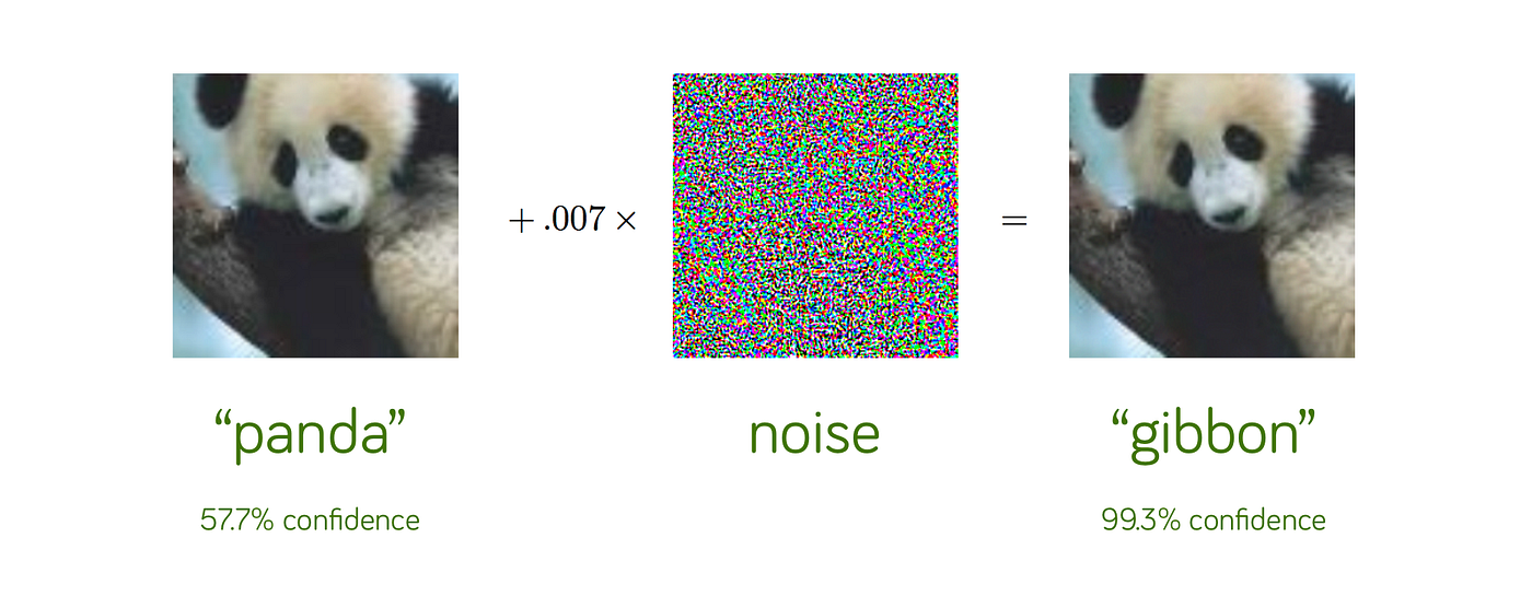
**:book:Adversarial Attacks**
Adversarial machine learning, a technique that attempts to fool models with deceptive data.
:::
:::info
**:book:Workflow of Detection Mechanisms**

:::
Existing deployments have some issues:
1. A separate accelerator is typically employed to run detection network model, which significantly increases hardware cost.
2. Reuse the same accelerator and run both target and detection network. However, the current accelerator architecture only allows the serial execution of the two, degrading system performance.
We believe that it is challenging to deploy adversarial sample defense methods in existing DNN accelerators.
## Goal
1. A new DNN accelerator architecture that can simultaneously execute target network and detect mechanisms.
### Key Features
1. ++High-bandwidth data sharing++: support data communication and synchronization of target and detection network
2. ++The need of CPU++: effectively perform the special computational operations required by the defense methods
3. ++Elasticity++: manage and schedule the computation and on-chip buffer resources needed by target and detection network
## DNNGuard Architecture Overview
A heterogeneous architecture which is composed of a CPU core and an elastic DNN accelerator.

### 1. On-chip buffer and management mechanism
On-chip buffer is the key to provide efficient data communication within DNN accelerator and the CPU.
:::info
**:book:Common communication method via system bus**
The communication method below may result in significant performance overhead and energy consumption.

:::
In addition, existing DNN accelerators typically adopt the design of static and one-way on-chip buffer. It causes copy and movement in data communication between the detection mechanism and target network.
:::info
**:book: The example for static and one-way on-chip buffer**
:::
#### The goals of elastic on-chip buffer management mechanism
1. **Reuse the shared OFmaps, effectively reducing the data transfer and improving the data communication efficiency between the target network and the detection mechanism.
2. Support for concurrent tasks.
3. Enforcing Read-After-Write dependence between tasks.

1. Multi-bank SRAM
Multiple SRAM banks are dynamically grouped togetheras a set to form the buffers (e.g., NBin_Target, NBout_target,SB_target of target network etc.). The granularity of static one-way buffer allocation is at the set level.
2. Status Register
Each physical bank contains four status registers (empty, full, write completion, read completion) to show its usage status. The status of the input and output buffer of the target and detection network includes BankWriteFinish, BankWriteDoing, NBinUsing, NBinReadComplete, NBinUnusing etc is used to solve task dependency issue.
### 2. Extended AI Instruction Set
The extendedAI instruction set includes three categories of instructions:
1. Configuration Panel
2. Data Panel
3. Control Panel
to meet diverse communication and data processing requirements.

### 3. Scheduler for task-level synchronization and resource scheduling
The detection network is required to run faster. Also, it is necessary to ensure that the detection network can obtain sufficient resources to process the data.
#### The main jobs of scheduler
1. Config resources by parsing and sending the extended AI instruction set
2. Monitoring the processing status registers and buffer status registers
3. Cooperating with the event queue to achieve efficient communication and task scheduling between elastic DNN accelerator and the CPU core
#### Event queue communication
It is designed to immediately respond to the accelerator request. CPU core processes special computation and sends the results and status of the processing to the scheduler.

The execution process of a typical detection network on the DNN accelerator and CPU.

### 4. Elastic PE Resource Management
Existing PE design is composed of Multiply-and-Accumulate (MAC)and Convolution Accumulator (CACC) with a single-channel design. Naturally, this structure is unable to support dual-model input-output or multi-model input-output. Also, existing PE structure does not support dynamical allocation for target and detection network.

#### New Components for PEs
- MAC Switch (MS) unit
An MS unit is added to the input port of PE to select the activation value or weight of the input of a certain network.
- Adder Switch (AS) unit
An AS unit is added to the output port of PE to select the computational output or partial sum of a certain network.
- Routing Logic unit
It guarantees the consistency of data input and output routes belonging to the same network.
### 5. Compiler Design
#### Goals
1. minimize off-chip accesses
2. maximize performance of target and detection network
#### Analytical model
A heuristic resource optimization search algorithm to optimize the scheduling and resource partitioning.
```c=
algorithm(dataflow_graph, data_dependency_of_models, dnnguand_hw_params)
{
int result_pe, result_buf;
int max_num_pe = dnnguand_hw_params.pe;
int estimated_pe, estimated_buf, estimated_cycles;
// the number of PEs and the on-chip buffer size for each layer
// the estimated execution cycles
estimated_pe, estimated_buf, estimated_cycles = initialization(dataflow_graph, data_dependency_of_models, dnnguand_hw_params);
num_pe = select_proper_pe(estimated_pe);
for num_pe < max_num_pe {
// search the proper on-chip buffer size and PEs
num_buff = search_proper_buff(estimated_buf);
// the execution cycle is evaluatedin the simulator based on the allocated resources
cycles = estimation(num_pe, num_buff);
if cycles < estimated_cycles {
estimated_cycles = cycles;
result_buf = num_buff;
result_pe = num_pe;
}
num_pe += 1
}
return result_pe, result_buf
}
```
## Evaluation

### Baselines

To make fair comparison, we re-implement NVDLA called Source-NVDLA (SNVDLA) which combines the large NVDLA and the small NVDLA together to run the target network and the adversarial network respectively. The elastic NVDLA (ENVDLA) has an equal amount of PE and on-chip buffer as the SNVDLA.
### Performance

The elastic NVDLA use synchronization and configuration instructions to dynamically adjust the resource allocation for better performance.
On average, the elastic NVDLA achieves around **1.42 speedup** over SNVDLA.
- dynamic resource allocation results in the performance improvement of about **18.4%**.
- data communication improves the performance of the elastic NVDLA by **32.1%**.
The elastic NVDLA integrates dedicated functional units and elastic resources management optimized for DNN techniques. The extension AI instruction also improves the utilization of on-chip buffer and PE resources, which is the major reason for the elastic NVDLA performance improvement.
#### The performance improvement of tightly coupled DNN accelerator architecture

#### Area

The scheduler, elastic on-chip buffer management mechanism and elastic PE resource management mechanism consume about 9.9% of the power.
### Sensitivity Analysis

#### a. The number of PE
While the number of PE increases from 64 to 2048, the computational performance does not increase linearly, so the elastic DNN accelerator does not need too many PEs.
PE utilization is close to 100% when the number of PEs is in the range of ++64~256++.
#### b. Buffer Capacity
The performance improvement is mainly limited by the DRAM bandwidth.
#### c. DRAM Bandwidth
AlexNet and VGG16 have higher sensitivity to DRAM memory due to heavy-weight full connection layers.
#### d. LLC ([Last Level Cache](https://en.wikichip.org/wiki/last_level_cache)) size of CPU
When LLC size is larger than 256KB, the performance of these defense methods does not increase correspondingly.
 Sign in with Wallet
Connect another wallet
Sign in with Wallet
Connect another wallet