---
tags: "Computer Network"
---
# Workshop 2: IPv6 transition mechanisms
### Kristoffer Plagborg Bak Sørensen, 201908140
### Pernille Sonne Pallesen, 201909457
[ [Back to Root page](https://github.com/rhjacobsen/CN_workshops/blob/master/README.md) ]
The goal of this workshop is to get hands-on experience with IPv4-IPv6 transition mechanisms. The workshop consists of two parts. The first part deals with simple IPv6-in-IPv4 tunnelling, while the second part explores a protocol translation mechanism.
TIP: You may consider to split the configurations into two different topology projects (labs).
## Part 1: Simple tunnel setup
We first consider the process of setting up a single IPv6-in-IPv4 tunnel. The IPv6-in-IPv4 tunnel allows connections to IPv6 networks through IPv4 networks. This is what is typically used today when connecting to IPv6 networks through the Internet.
### Lab overview
#### Network topology
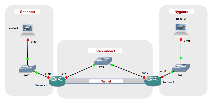
#### Networks
| Name | Network
|--------------|--------------------------
| Interconnect | 10.0.0.0 / 24
| Shannon | 2001:878:402:1::0 / 64
| Nygaard | 2001:878:402:2::0 / 64
| Tunnel | 2001:878:402:3::0 / 64
### Creating the lab
The laboratory shall be configured with the following IP addresses:
| Network Node | eth0 | eth1
|---------------|------------------------|------------------
| Node-1 | 2001:878:402:1:XX / 64 | N/A
| Node-2 | 2001:878:402:2:XX / 64 | N/A
| Router-1 | 2001:878:402:1::1 / 64 | 10.0.0.1 / 24
| Router-2 | 2001:878:402:2::1 / 64 | 10.0.0.2 / 24
An XX in an IPv6 address means that the interface is configured using stateless autoconfiguration and will configure an address with the prefix given to the router on the corresponding network. You may what to consult Workshop 1 to recap how this is done.
Try to ping following:
* Router-1 (eth0) <-> Node-1 (eth0)
* Router-1 (eth1) <-> Router-2 (eth1)
* Router-2 (eth0) <-> Node-2 (eth0)
This should work without any problems when the interfaces have been configured correctly.
> ##### Challenge 2.1
> Explain why you cannot ping eth1 of "Router-1" from "Node-1"?
> ```
> The connection from Node-1 to Router-1 is on the eth0 of Router-1.
>
> eth1 from Router-1 is connected to SW1.
> ```
### Tunneling
Now, we setup a 6-in-4 tunnel between "Router-1" and "Router-2", such that "Node-1" and "Node-2" can communicate using IPv6.
Login to "Router-1" and execute the following commmand:
iptunnel add tun0 mode sit ttl 64 remote 10.0.0.2 local 10.0.0.1
This will create a virtual network interface called tun0. The tunnel uses sit mode, which stands for Simple Internet Transition. Packets sent to the interface are encapsulated in IPv4 packets and send to the remote endpoint (10.0.0.2). IPv4 packets containing IPv6 packets received on the local endpoint (10.0.0.1) are decapsulated and delivered through the tunnel interface. The ttl 64 specifies that the TTL of the generated IPv4 packets is to be set to 64.
Setup an IPv6 address on the tun0 interface:
ip addr add 2001:878:402:3::1/64 dev tun0
ip link set up tun0
Note that we are using a new network prefix rather than one of the two already used. This makes the interface easier to use, as all packets for the 2001:878:402:3/64 prefix are automatically routed to the tun0 interface.
Login to "Router 2" and create the other endpoint of the tunnel:
iptunnel add tun0 mode sit ttl 64 remote 10.0.0.1 local 10.0.0.2
ip addr add 2001:878:402:3::2/64 dev tun0
ip link set up tun0
Ensure that you can ping 2001:878:402:3::1 from "Router 2".
> ##### Challenge 2.2
> Currently, it is not possible to ping 2001:878:402:1::1 from "Router 2". Briefly explain why.
> ```
> The IP address "2001:878:402:1::1" is the routers connection to the
> Shannon network, which is why it can not be pinged from anywhere in the
> interconnection.
> ```
On "Router 1" add a route to the 2001:878:402:2::/64 network by running:
ip -6 route add 2001:878:402:2::/64 via 2001:878:402:3::2
On "Router 2" add a route to the 2001:878:402:1::/64 network:
ip -6 route add 2001:878:402:1::/64 via 2001:878:402:3::1
Ensure that you can ping 2001:878:402:1::1 from both "Router-2" and "Node-2".
Use the command ```ip -6 route``` to inspect the routing tables on "Router-1" and "Router-2", and observe how the tunnel endpoints are being used as interfaces.
Lastly, add the default route on Node-1
ip -6 route replace default via 2001:878:402:1::1
and Node-2
ip -6 route replace default via 2001:878:402:2::1
Start Wireshark, and capture packets from the IPv4 Network: Interconnect. Ping "Node-2" from "Node-1".
After a couple of ping requests have been answered, stop the ping and Wireshark capture.
Inspect the ping packets captured.
> ##### Challenge 2.3
> Explore and briefly explain the structure of the ping packets captured using Wireshark.
> ```
> The ping command uses the ICMP protocol and Node-1 sends a ICMP request
> message to Node-2. Node-2 receives this message, and replies back using
> the ICMP reply message, to notify the sender that it is reachable.
> This back and forth communication is repeated 5 times, as the ping
> command runs 5 iterations.
>
> Inspecting one of the messages, we see that when the message reaches the
> router (i.e. the start of the tunnel), the IPv6 packets are encapsuled
> in in IPv4 packets. When it then reaches the other router (i.e. the end
> of the tunnel), the packets are decapsuled again.
>
> To make sure that the IP has not changed in the meanwhile, the
> ARP-protocol runs. If it has changed, the IP-MAC-mapping can be
> updated.
> ```

Stop the laboratory.
## Part 2: Protocol translation
In this part, we will use protocol translation mechanisms to provide interworking between IPv6 and IPv4. We will use a mechanism calles stateless NAT64 (actually it is SIIT). On Linux this is provided by the Tayga software package.
TAYGA is an out-of-kernel stateless NAT64 implementation for Linux that uses the TUN driver to exchange IPv4 and IPv6 packets with the kernel. It is intended to provide production-quality NAT64 service for networks where dedicated NAT64 hardware would be overkill.
### Lab overview
#### Setup
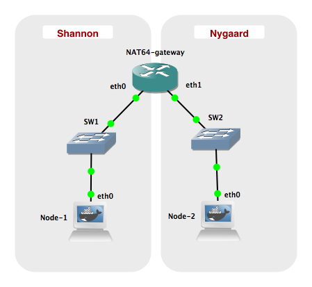
#### Network
| Name | Network
|------------------|--------------------------
| Shannon | 2001:db8:1:1::0 / 64
| Nygaard | 192.168.1.0 / 24
| Nygaard IPv6 NAT | 2001:db8:1:ffff::0 / 96
| NAT Pool | 192.168.255.0 / 24
### Creating the lab
Configure the interfaces given in the table below:
| Network Node | eth0 | eth1 |
|---------------|----------------------|------------------|
| Node 1 | 2001:db8:1:1::2 / 64 | N/A |
| Node 2 | 192.168.1.2 / 24 | N/A |
| NAT64 gateway | 2001:db8:1:1::1 / 64 | 192.168.1.1 / 24 |
### NAT64 with Tayga
Before starting the TAYGA daemon, the routing setup on your NAT64 gateway will need to be changed to allow sending IPv4 and IPv6 packets to TAYGA.
Make a configuration file ```/usr/local/etc/tayga.conf``` with the following content:
tun-device nat64
ipv4-addr 192.168.255.1
prefix 2001:db8:1:ffff::/96
dynamic-pool 192.168.255.0/24
data-dir /var/spool/tayga
Then create the TUN network interface.
tayga --mktun
Enable datagram forwarding on interfaces on NAT64 gateway:
sysctl -w net.ipv6.conf.all.forwarding=1
sysctl -w net.ipv4.ip_forward=1
Define a new interface on the NAT64 gateway and assign an IPv4 as well as an IPv6 address to the interface:
ip link set nat64 up
ip addr add 192.168.0.1 dev nat64
ip addr add 2001:db8:1::1 dev nat64
Setup static routes to ensure that traffic is routed to the new interface.
ip -6 route add 2001:db8:1:ffff::/96 dev nat64
ip route add 192.168.255.0/24 dev nat64
Finally, start the NAT64 gateway application by using the command
tayga -d &
Inspect the new interface by using ifconfig nat64. On the NAT64 gateway try to ping6 2001:db8:1:ffff::192.168.0.1. If it succeeds, Tayga is running properly.
Add default gateway routes to Node-1 and Node-2, respectively:
ip -6 route replace default via 2001:db8:1:1::1 (Node 1)
ip route replace default via 192.168.1.1 (Node 2)
> ##### Challenge 2.4
> Try to ping Node-2 from Node-1. What address should you ping and what is the results?
> ```
> We should ping "2001:db8:1:ffff::192.168.1.2" since it has the prefix
> from the gateway and the IPv4 address from Node-2.
>
> As seen before, Node-1 sends ICMP request messages and Node-2 responds
> with ICMP reply messages.
> Both the request and reply messages uses IPv4.
>
> The request messages has a source IP adress from the dynamic IPv4 pool,
> as it orginally has an IPv6 adress.
> ```

> ##### Challenge 2.5
> Inspect the file /var/spool/tayga/dynamic.map and explain its content and function?
> ```
> It has a table of the local IPv4 adresses that are used by IPv6 nodes.
>
> It keeps track of which IPv4 addresses are in use, and saves this
> information so the same mapping is kept after a restart.
> ```
The program tcpdump can be used as an alternative to Wireshark for capturing packets. Packet capture files can be stored and loaded into Wireshark for a more user-friendly presentation. An example of use is ```tcpdump -i eth0 -w mycapture.pcap```, that will dump all packets that passes the eth0 interface to the file mycapture.pcap.
TIPS: You may use ```tcpdump -c 5``` to limit the number of packets (e.g., 5 packets) to be captured. Note also that the ```tcpdump -r``` option allows you to read a .pcap file and print it to the console.
## VI HAR RETTET VORES BESVARELSE HERUNDER
> ##### Challenge 2.6
> Capture packets sent over the nat64 interface. Explain the content of the packet capture and clarify the main differences from a similar setup using 1) pure IPv4 networking and 2) pure IPv6 networking.
> ```
> The TCP packet capture on the NAT64 shows the indirection and translation that
> the tayga daemon does to enable bidirectional IPv4 to IPv6 communication.
> In the simulation Node 1 pings Node 2 using the IPv6 address from challenge
> 2.4. The echo request is captured on the NAT64, and it is using ICMP6 since,
> the ping request is sent to the "virtual address" on the tayga,
> which maps to the IPv4 on Node 2's eth0.
> On the second line we can see that the tayga software translates this
> to an ICMP echo request using IPv4. Both the sender and receiver address
> of the IP is changed here to IPv4.
> Node 2 receives the package and replies with an ICMP echo reply message
> to the virtual address of the tayga which it "believes" it received it from.
> Finally on line 4 the reply is mapped back to an ICMP6 echo reply
> message and sent to the IPv6 address of Node 1 eth0.
>
> The gateway can bee seen as a translator, which makes it possible to do
> networking with both IPv4 and IPv6 in the same network. But if the network
> is purely IPv4 or purely IPv6, this translation becomes irrelevant, and
> the gateways only job would be to forward messages.
> ```
**TCP capture on NAT64**

**The ping command used when capturing packets on NAT64**

<!-- > We have made two packet captures on Node-1 and Node-2 respectively. -->
<!-- > The first one is on Node-2, which uses IPv4. This can also be seen from -->
<!-- > the sender and reciever address in the TCP dump, where the sender is -->
<!-- > Node-2 and the reciever is the IPv4 address which Node-1 has borrowed -->
<!-- > from the NAT64-gateway. -->
<!-- > -->
<!-- > The second one is on Node-1, which uses IPv6. This can also be seen from -->
<!-- > the sender and reciever address in the TCP dump, where the sender is -->
<!-- > Node-1 and the reciever is the IPv6 address that has been assigned -->
<!-- > to the NAT64-gateway. -->
<!-- IPv4: -->
<!--  -->
<!-- IPv6: -->
<!--  -->