###### tags: `TA Stuff 2021` `Pycom` `ESP32`
# Tutorial 2: Project & Sensor Setup
This tutorial is aimed at giving you a general overview on how to work with sensors and read them from your device.
We will:
* Start off by explaining how to organize your code in a project
* Explain how your lopy4 works and the different protocols available
* How to connect a sensor physically
* How to work with analog sensors
* How to work with simple digital sensors
* How to use libraries for sensors, especially more advanced sensors
**If you want to learn more about the basics of electricity and circuits** before heading onwards to connecting sensors, check out [this awesome course on Khan Academy](https://www.khanacademy.org/science/physics/circuits-topic).
This tutorial will be used in the next week's workshops as well, we'll stay on this topic for a bit longer. (But if you're ahead, feel free to head start into [connecting to Wi-Fi](https://docs.pycom.io/tutorials/networks/wlan/) and then [sending sensor data to Pybytes](https://docs.pycom.io/pybytes/gettingstarted/).)
As always, we'll continously update this walkthrough. **Is there anything missing or unclear, or you experience some issue? Please add a comment.** You do this by highlighting the text and then you can write a comment on the highlighted part. You need to log in/create account on hackMD first.
## The file hierarchy used in projects
When creating a new project there is a standard structure to follow:
```
Your_project_name
|-lib
| |-library.py
|-boot.py
|-main.py
```
Note that `boot.py` and `main.py` are outside of `lib` while `library.py` is inside of `lib`. All of them are, however, inside the project folder `Your_project_name`.
In the respective IDEs, Atom and VS code, the same structure will look like this:
Atom project | VSC project
:-------------------------:|:-------------------------:
 | 
* The `lib` folder will hold libraries, that is, code files you may have use of in your project. This could for example be sensor libraries; already written code that makes it easy for you make sense of sensor's output data. Read more about how you import libraries and use them under [Sensors that require a library](#Sensors-that-require-a-library) and [How to import library](#How-to-import-library).
* The `boot.py` file is the first script that runs in the device when it is powered on. It could be used for setting up a WiFi connection, and thus declutter the main file where this code otherwise would be placed. Most often you don't have to worry about this file.
* The `main.py` file is where you tell the device what to do. It will run directly after the boot file. This is the place for your main code and where you may use files in the lib folder.
### Creating a new project
You may create a new project and this file structure by doing the following:
* First you will open a new folder by clicking `File > Open Folder`. This will lead you to your file explorer, now create a new folder and name your project. Select this folder and open it.
* Now, inside the project manager area, right-click on your mouse or mousepad and select file or folder to name and create them. It is also possible to create files from `File > New File`, just remember to save it in the right folder.
Atom project | VSC project
:-------------------------:|:-------------------------:
 | 
## Your Lopy4 Device
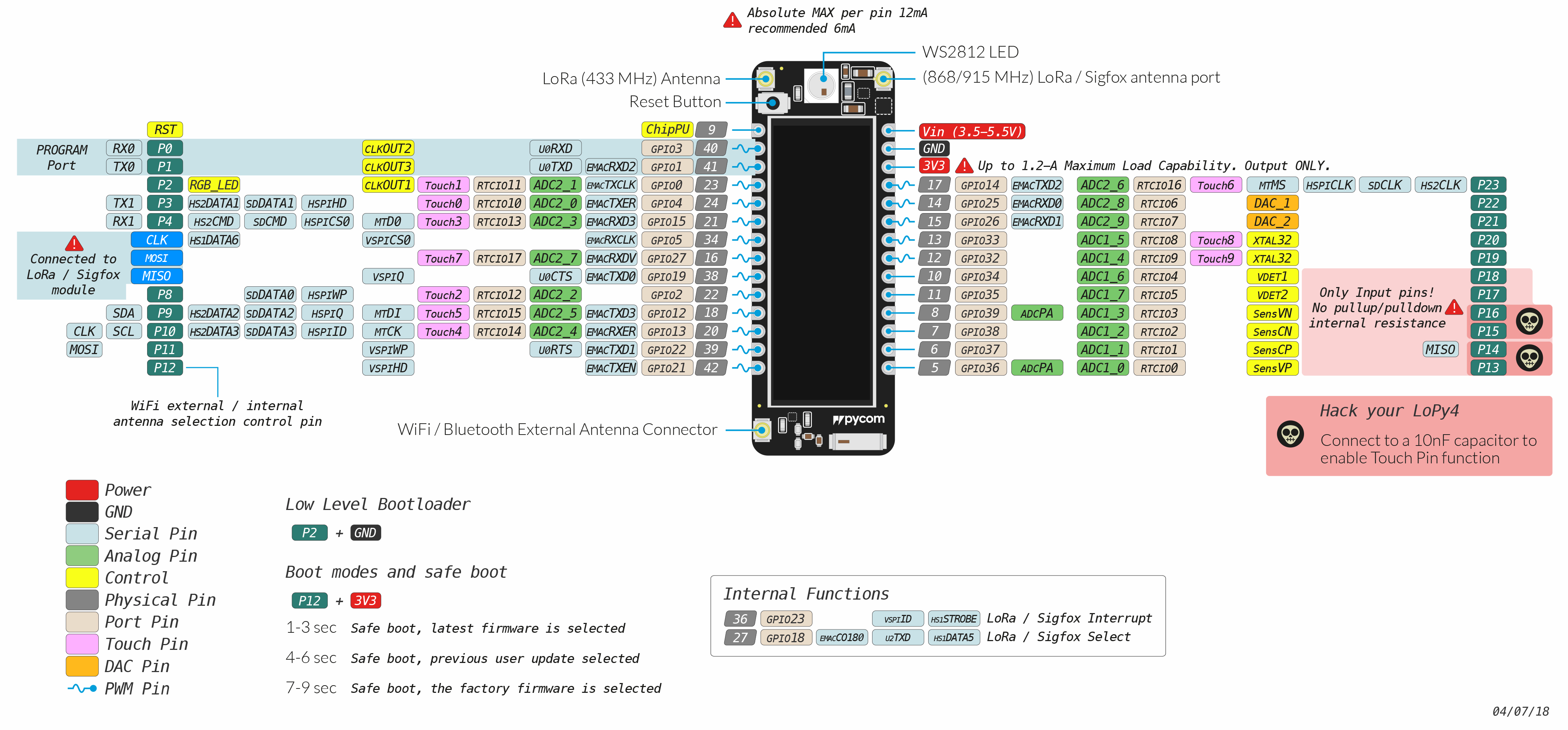
This is your lopy4 device (pdf available [here](https://docs.pycom.io/gitbook/assets/lopy4-pinout.pdf)). It's a complex schematic with lots of different pins and functions. You will regularly come back to this and eventually familiarize yourself with it (For the fipy pinout see [this](https://docs.pycom.io/datasheets/development/fipy/)).
(**⚠️ When referring to a pin in this tutorial, we don't mean the grey physical pins, but the turqoise pins noted `P23`, `P24` etc, which is the same pins on the expansion board.**)
### Analog to digital
What you might look at first are the green **Analog Pins**. This is called `ADC_#` in the schematic. ADC stands for Analog to Digital Converter - and what it does is taking an input signal from your sensor, and converting it to a digital representation - something the computer can work with.
The difference between analog and digital is that **analog** signals *vary*, they go anywhere between 0 and some other voltage, for example 3.3V (or 5V); while **digital** signals are either 0 or that voltage - which means they are binary, _low_ or _high_ voltage - or in computer language, `0` or `1` (_false_ or _true_).
You computer works in binary, that's why we need an analog to digital converter to work with the signals. To interface it you use the `ADC()` in the code (Learn how to use analog sensors and ADC [**here**](https://hackmd.io/S-2kPmXSRIGPSJAvmSwnfw?both#Basic-Analog-sensors))
### General purpose pins
As you might note all the analog pins are also beige **Port Pins** and in the schematic `GPIO`. This stands for General Purpose Input/Output, which means it can be used by the `Pin()` in the code, for example with a basic digital sensor. (Learn [**here**](https://hackmd.io/S-2kPmXSRIGPSJAvmSwnfw?both#Basic-digital-sensors) how to use it)
### Advanced functionality
These are more advanced and we don't expect you to learn this, but if you've got sensors or building a project that needs to use them, we've explained how they work here.
#### **I2C**
I2C is a protocol for communication with multiple devices.

It uses two wires: a data wire (SDA) and a clock wire (SCL). These are [pulled up](https://en.wikipedia.org/wiki/Pull-up_resistor) with resistors (high voltage from Vdd), to ensure a high state per default. Each device is connected to these two wires.
A device is either a master or a slave:
* **A master device:** *initiates communication* and *determines the clock frequency*
* **A slave device:** *receives communication* from the master device
How to interface it on your Pycom [**here**](https://docs.pycom.io/firmwareapi/pycom/machine/i2c/). Learn more about how I2C works [**here**](https://www.youtube.com/watch?v=6IAkYpmA1DQ) and how to connect it.
#### UART

How to interface UART on your pycom [**here**](https://docs.pycom.io/firmwareapi/pycom/machine/uart/). UART explained clearly here:
{%youtube V6m2skVlsQI %}
#### Others
All protocols for the pycom listed [**here**](https://docs.pycom.io/firmwareapi/pycom/machine/) and how to interface them.
## How to connect a sensor physically
The basic sensors are generally quite easy to connect to the lopy. They usually have 3 pins, one to connect 5V or 3.3V to, another to connect to ground (GND, 0V) and one to measure from.
For example, to connect a TMP36 analog temperature sensor you could do as follows:


Connect the positive voltage leg to `3V3`, the ground leg to `GND` and the output leg to any pin with ADC capabilities (in this case, `P16`).
**⚠️Important⚠️ Some sensors have a flat and a curved face. For example the TMP36 sensor mentioned above. Make sure to connect them in the same way as the pictures since you otherwise they might burn out.**
To connect your sensors to the lopy, a breadboard is very useful.
They usually contain 2 longer rails on each side, to easily connect to $V_{dd}$ (Positive voltage, operating voltage) and __GND__ (ground, 0V) to all your components.
Each row of a breadboard is numbered and contains a rail, to easily allow you to connect pins and wires.
### Sensor connection examples
Here's an [**album of some connections that we've made for common sensors and output devices**](https://imgur.com/gallery/DT0jhg6).
You can make your own diagrams like the ones above using the program [**fritzing**](https://fritzing.org/).
If your sensor isn't in the album, then it's recommended that you read the datasheet of the sensor to figure how to connect it. This can often be found from same page you bought it, Electrokit often provides datasheets or tutorials. [**Like this one, check it out!**](https://www.electrokit.com/uploads/productfile/41015/User_guide.pdf) If there's no available, try searching the sensor name + datasheet or tutorial.
**If your sensor needs 5V** (often 3.3V works even when it's not specified) you can use the `Vin` port if your device is connected via USB to your computer (`Vin` is just the voltage that goes into your device, USB is 5V).
## Basic Analog sensors
Analog sensors are devices that produce analog output. These sensors observe the change in external factors such as light intensity, speed of the wind, solar radiation, and others. The output of an analog sensor generally ranges between 0V to 5V (or 3.3V).
In this section we want to show you a typical example of how to do this in micropython. For this example we'll use the [TMP36](https://www.electrokit.com/produkt/tmp36-to-92-temperaturgivare/), an analog temperature sensor. (It's similar to temperature sensor MCP9700 which followed in the electrokit bundle)

First thing we want to do is to create an [ADC](https://docs.pycom.io/firmwareapi/pycom/machine/adc/#app) object for analog to digital conversion. This is the "thing" in our code we'll use to read from our sensor.
```python
import machine
adc = machine.ADC()
```
Next off, we want to define where we want our `adc` to collect its input from, that is, which pin our temperature sensor is connected to on the Expansionboard.
```python
apin = adc.channel(pin='P16')
```
In this case, we've connected it to pin 16, written as `P16`. Different pins do different things. If you feel adventurous, you can read up on what all pins do [here](https://docs.pycom.io/gitbook/assets/lopy4-pinout.pdf).
We can now read our sensor.
```python
millivolts = apin.voltage()
```
This reading comes as millivolts. In order to actually gather some useful data out of this we have to convert it. This is common in the world of analog sensors, and in order to know how to convert the sensors output into something useful, we have to read its [datasheet](https://www.electrokit.com/uploads/productfile/41012/41012431.pdf) (or use Google).
In the datasheet we find our conversion:
$$
celsius = {millivolts - 500\over10}
$$
Now we can make this into actual runnable code on our LOPY4's!
Check this out!
```python
import machine
import time
adc = machine.ADC()
apin = adc.channel(pin='P16')
while True:
millivolts = apin.voltage()
celsius = (millivolts - 500.0) / 10.0
print(celsius)
time.sleep(1)
```
This is just an example for an analog temperature sensor, however reading from another kind of simple analog sensor would only differentiate in the last step where we convert from millivolts.
## Basic digital sensors
[//]: <> (
AP6: Erik Brink
Switch, anything that does either HIGH/LOW
//TODO: Add concise tutorial. With code? Explain what makes a digital sensor
)
Contrary to analog sensors, digital sensors only output high or low - also known as the binary values `1` or `0`; in layman's terms, the sensor is either "on" or "off" (more advanced digital sensors, such as the DHT11/22, outputs a series of 1's and 0's which the pycom interprets - often requiring a [library](https://hackmd.io/S-2kPmXSRIGPSJAvmSwnfw?both#Sensors-that-require-a-library-AP-7-8-David-Mozart-amp-Abbe)).
They could be anything from a basic tilt switch to a movement sensor. A prime example of a digital sensor is a [knock sensor](https://www.electrokit.com/en/product/knock-sensor/) (See figure below from Electrokit).

The knock sensor detects, as you can imagine, knocks and vibrations. The middle pin needs to be connected to **5V** (3.3V might also work) and the pin denoted with a "**$-$**" should be connected to **Ground** (**GND**). If the sensor detects any vibrations, the pin denoted with an "**S**" is set to `0`. If *no* vibrations are detected, it is set to `1`. It is therefore pretty straight forward to extract the information from the sensor.
```python=
from machine import Pin
import time
pin_input = Pin('P16', mode = Pin.IN)
# This pin is the "S" pin as mentioned above
while True:
value = pin_input.value() # Get the value, either 0 or 1
if value == 1:
print('No vibration detected')
else:
print('Vibration detected')
time.sleep(0.1)
```
The code above continuously checks if the sensor has been disturbed. If it has been disturbed, the string `Vibration detected` is printed. Let's dissect the code into smaller pieces in order to understand what is happening:
```python
from machine import Pin
import time
```
Firstly we need to import the necessary micro-python modules. The [`Pin` module](https://docs.pycom.io/firmwareapi/pycom/machine/pin/) let's us access the LoPy's data pins.
```python
pin_input = Pin('P16', mode = Pin.IN)
```
The code above has created a `Pin` object. The chosen pin (`P16`) needs to be set as an input from the sensor. We therefore set the mode of the pin to `Pin.IN`.
```python
while True:
value = pin_input.value() # Get the value, either 0 or 1
```
By entering an infinite loop, we can check continuously for updates from the sensor. We extract the value by typing `value = pin_input.value()`, where `pin_input` is the variable name for our pin and `value()` is the function that return the value of the pin (`1` or `0`).
```python
if value == 1:
print('No vibration detected')
else:
print('Vibration detected')
```
We then check the value form the sensor in order to determine what message to print.
```python
time.sleep(0.1)
```
Lastly, we let $0.1$ seconds pass before a new read from the sensor.
## Sensors that require a library
These are often more advanced sensors, but can also be basic and the libraries just make life easier. In this section, we demonstrate how to use sensors that requires a library.
### How to download libraries
In our gitlab there exist some libraries for some sensors which you can use.
To download them you go to this [**repository**](https://gitlab.lnu.se/1dt305/sensor-libs) (you need to login with your lnu account) and follow the arrows in the below picture. If your sensor does not have a library in our repo, you can try looking for one online or ask one of the teaching assistants for help.

After downloading the zip-folder you need extract the downloaded files.
### How to import library
To use the downloaded library, you simply copy the content of lib in the extracted folder and paste it under your lib folder, as demonstrated [here](#The-file-hierarchy-used-in-projects).
Once done, your project should look similar to the one shown below.

In each sensor folder you will find a library (the lib folder) and example code that run or use it, if they require a library to run.
### Use the library
You can create your own main file that uses the lib. All you need to do is to import the library in [main.py](#). You may import the library from lib in 3 different ways:
```python=
import library #imports the whole library file,
#everything is accessible through dot-notation
from library import className #only import a specific part from the
#library
import library as newName #imports the whole library file, however,
#the library is renamed in this file
```
For example, the code below uses the LiDAR library. Read the comments in the code to learn how it uses the library. The datasheet can be found [here](http://myosuploads3.banggood.com/products/20200515/20200515021121SJ-PM-TF-LunaA03ProductManual.pdf).
```python=
# Import necessary modules and our own LiDAR library
from machine import I2C
import utime
import sys
from lib.lidar import LIDAR # Our LiDAR library
# From the TF-luna datasheet, we learn that
# the sensor has the adress 0x10
LIDAR_ADDRESS = 0x10
# We create an I2C bus, to which we connect our LiDAR
# P7 = SDA of the sensor
# P8 = SCL of the sensor
i2c_0 = I2C(0, mode=I2C.MASTER, baudrate=400000, pins=('P7', 'P8'))
utime.sleep_ms(50)
# We scan the bus for sensors
# Note that multiple I2C sensors can be found
# if they're connected to this bus (bus 0, P7 & P8)
slaves = i2c_0.scan()
if LIDAR_ADDRESS not in slaves:
print('Bus error: Please check LIDAR wiring')
sys.exit()
# We create a sesnor object, defined in our library
lidar = LIDAR(i2c_0, LIDAR_ADDRESS)
lidar.set_min_max(20, 150)
lidar.set_frequency(250)
# We print the distance every 10 milliseconds in an infinte loop
while True:
print(lidar.distance())
utime.sleep_ms(10)
```
Your code will look something like this in Atom

<style>
.markdown-body img{
display: block;
margin-left: auto;
margin-right: auto;
}
</style>
## Connect multiple sensors
Connecting multiple sensors works just like connecting one sensor. You could use the **+** rail on the breadboard where you connected your voltage output from your device, and the **-** for GND. The rail goes along the whole breadboard so you can connect several sensors from these rails.
**⚠️IMPORTANT⚠️ Disconnect the power/USB cable from the lopy/expansion board before connecting. This allows us to check that everything is correct before powering the board.**
**We recommend using colored wires to make it easire to distinguish which wires are which**


In the example we are connecting 3 different kind of sensors/actuators. The first one from the right is the simplest. It's a hall effect sensor (analog). Next is the DHT sensor that measure temperature and humidity. It requires a library to communicate with it. Last but not least we have and Oled display (SSD1306) that uses the I2C protocol. Although it's not a sensor it connects like any other I2C sensor using the SCL and SDA pins.
We can now start connecting sensors. We start by connecting the analog hall effect sensor. We can pick any pin that has An analog to digital converter but make sure to use ADC1 instead of ADC2 (marked in the pinout) since ADC2 is used for wifi on the lopy4.

Now we can move on to connect the signal pin of the DHT sensor. We can use any input digital pin but make sure to pick one that doesn't have any other usages that might conflict with the sensor. We pick pin P20 since it is right after the previous one for a tidier diagram.

Now we can connect the display. For I2C we have to use 2 specific pins. They are marked as SCL and SDA in the pinout diagram of the lopy4. We can actaully use the same 2 pins for multiple I2C sensors without a problem, but that only applies to I2C (and SPI) sensors.
The SDA pin on the lopy4 is P9 and the SCL pin is P10 so we connect to those pins.

**⚠️Double and triple check The connections before connecting power.**
If all the connections are correctly in plac then all that is left to do is to write/modifiy the code with the pins we have just connected.
<br/>
:::info
**Credit**
Written by David Mozart, Linnea Allander, Erik Karlsson, Abdulsalam Aldahir, Mohammad Qasem, Erik Brink, Love Lyckaro, Christoffer Eid
:::