---
tags: 單晶片
---
# Arduino講義:Serial Communication (I2C)
---
<!-- > **重點 or 縮寫** 請標**黑粗** 且 英文記得空格ㄚㄚㄚㄚ -->
<!-- > -->
<!-- > [name=YuanHaoHo][color=#c8ff05] -->
## Introduction of I2C
* I2C bus 為 Inter-Integrated Circuit Bus 的縮寫,中文叫做積體電路匯流排,其功用為提供 IC 之間的連接與通訊。
* 目的:減少MCU與周邊晶片之間的腳位數
* 只有兩條訊號線,<font color="red">SCL(Serial CLock Line) 負責傳時脈,SDA(Serial Data line)負責傳資料</font>。
* **I2C** : <font color="red"> 半雙工、串列、同步</font>
* 以匯流排型介接允許有多個master以及slave。

* 由上圖可知,所有I2C裝置皆並接(Wired-AND)在SCL及SDA兩條線路上
* 須接<font color="red">上拉電阻(Rp)</font>,將浮接狀態( float )轉變為邏輯高準位( High )狀態。
## I2C Bus協定
* 閒置( idle )時兩者皆為高電位。

* START condition:<font color="red">SCL為 HIGH時,SDA發生下緣</font>
* 先傳地址( slave address,決定跟哪個 slave 溝通),再傳資料。地址有 7bit跟 10bit兩種。
* 7bit:最大可以有 128個 slave (但實際上有16個系統擴充位址是保留的)。
* 10bit:最大可以有 1024個 slave 。(但很少見,不是所有使用 I2C 的裝置都支援 10bit mode)。
* 地址:由於地址為 7bit,因此在傳第一個 byte的時候,前 7bit(MSB 為 address,最後的 bit 為 R/W bit,指定要"讀"或"寫"資料(0:write,1:Read)。
* 只在 <font color="red">SCL 為 HIGH 時,才會對 SDA 取樣。 SCL 為 LOW 時,不會取樣,但可改變資料</font>。
* STOP condition:<font color="red">SCL為 HIGH時,SDA發生上緣</font>
## ACK/NACK機制
* 發送端在每組(8bits)訊號送出後,需讀去接收端所回應的一個ACK bit(Acknowledge bit)
<font color="red">(注意:發送端不一定是master,ex:讀取資料時,發送端為slave)</font>
## 實際傳輸的狀況
* 寫入:

* R/W為0時,代表 slave 端要讀取master端資料,此時 slave 會發出一個 ==acknowledge bit==(就是由 slave 把 SDA 拉低),讓 master 確認 slave 是否有收到資料。
* 讀取:

* R/W 為1時,代表 master 端要讀取 slave 端資料,此時 master 為 Receiver,slave 為 transmiter,因此 acknowledge bit 會是由 master 進行發送。
:::info
note:傳地址後的 acknowledge bit 必為 slave 傳送給 master;傳送 Data 後的 acknowledge bit 則須視前面 R/W 的值而定。
:::
* 當 master 讀到 ACK 回應, 即可以繼續傳輸下一個 Byte。
* 當 master 讀到 NACK 回應, 意思是 **slave 無回應**,此時 master 應送出 (結束) 訊號放棄該命令。
* 參考資料:
* [資料來源1](http://i2c.info/i2c-bus-specification)
* [資料來源2](http://magicjackting.pixnet.net/blog/post/173061691-i2c-bus-%E7%B0%A1%E4%BB%8B-(inter-integrated-circuit-b))
---
#### Wire函數:
| 函數 | 作用 |
| --- | --- |
| begin()| 啟動 Wire 作為 master 或是 slave |
| beginTransmission(address)| 開始對 address 的連線 |
| endTransmission() |關閉之前的連線 |
| write(data) | 在連線上送出 一個 byte 的資料 |
|read() | 讀取連線上的一個 byte 的資料 |
|available() | 檢查連線上是否有可接收的資料 |
|onReceive(function) | 設定用來接收資料的函數 |
:::info
note:在無(address)時,Arduino 是作為I2C的 master;有(address)時,是作為 I2C 的 slave 。
:::
<!-- :::info
note: Arduino 沒有 I2C ,只有**2 wire serial interface(TWI)** ,但是這個TWI**相容於飛利浦的I2C協定**。詳見 [ATmega328P datasheet](http://ww1.microchip.com/downloads/en/DeviceDoc/Atmel-42735-8-bit-AVR-Microcontroller-ATmega328-328P_Datasheet.pdf) p.260。
::: -->
## LAB1
* 實驗目標:利用I2C進行Arduino間通訊
* schematic:
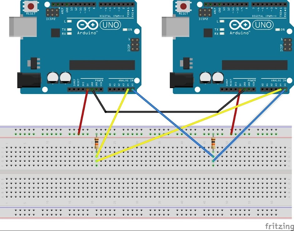
* master 把串口收到的資料,發送給 slave:

* slave 端直接處理接收回來的資料:

:::warning
若使用的 Arduino IDE 版本不能同時開兩個 Serial Monitor,請[點此](http://ttssh2.osdn.jp/)下載Tera Term後,點選設定做為第二個Serial Monitor。
使用方法:開啟Tera Term後,點選**設定** -->**連接埠** -->**更改端口與鮑率**
:::
# Arduino講義:LCD
## LCD介紹
* 目前市面上的 LCD 模組可分文字型及繪圖型兩種。文字型 LCD 模組常見的規格有16 字x1 行,20 字x1 行,40 字x1 行,16 字x2 行,20 字x2 行,40 字x2行等多種。
* 文字型 LCD 顯示器內部具有字元產生器,因此可以接受 ASCII 字元碼,並將字元顯示在 LCD 上。
## LCD架構
* LCD 模組的結構如圖所示,由 LCD 控制器、LCD 驅動器及 LCD 顯示器所組成。目前市售 LCD 模組所採用的 LCD 控制器都相容,使用方法也相同,因此幾乎所有的 LCD 模組都具有相同的控制方法。
## I2C 16x2 LCD介紹

* SDA – 接 Arduino 的 Analog Pin 4 (Arduino Mega 為 Pin 20)
* SCL – 接 Arduino 的 Analog Pin 5 (Arduino Mega 為 Pin 21)
* GND – 接 GND
* VCC – 接 +5V
## LCD接法

## 學習使用LCD貼出字串
* LCD I2C Libraries下載:[here](https://drive.google.com/file/d/11hV6xfWycVe5Hg2bahq_UgWgoPMLBCK9/view?usp=sharing)
* Keypad Libraries下載:[here](https://drive.google.com/file/d/1mnzf--VuktjYytxyOUm0J5sxz0J_YV6g/view?usp=sharing)
--> 解壓縮後將資料夾放進Arduino libraries當中
* code:

## LAB2
* 實驗目標:將上面的字串改成自己的學號,使其以如下影片的跑馬燈方式繞行。
* #### LiquidCrystal_I2C:
| 函數 | 作用 |
| --- | --- |
| lcd.begin(cols, rows); | 定義LCD的長寬(n列×n行) |
| lcd.clear() | 清空LCD |
| lcd.setCursor(col, row); | 設定輸入值起始位置 |
| lcd.print(data); | 在螢幕上顯示資料 |
| lcd.scrollDisplayRight(); | 將畫面向右捲動 |
| lcd.scrollDisplayLeft(); | 將畫面向左捲動 |
* 參考影片:
<iframe width="800" height="600" src="https://www.youtube.com/embed/5w0y1xAFMtc" frameborder="0" allow="accelerometer; autoplay; encrypted-media; gyroscope; picture-in-picture" allowfullscreen></iframe>
## LAB3
### 簡易計算機
* 實驗目標:利用薄膜鍵盤與LCD實現簡易計算機
* 實驗要求:
* A 鍵為加號、B 鍵為減號、C 為乘號、D 為除號、# 為等於、* 為清除鍵。
* 由薄膜鍵盤輸入數字後,LCD 第一列顯示運算式,第二列顯示等號與運算結果。
* 示範影片:
<iframe width="800" height="600" src="https://www.youtube.com/embed/-bGQgrrkhio" frameborder="0" allow="accelerometer; autoplay; encrypted-media; gyroscope; picture-in-picture" allowfullscreen></iframe>
## LAB4
### 四則運算計算機
* 實驗目標:加強計算機的功能,使其能進行四則運算
* 示範影片:
<iframe width="800" height="600" src="https://www.youtube.com/embed/6is9SvDOb7o" frameborder="0" allow="accelerometer; autoplay; encrypted-media; gyroscope; picture-in-picture" allowfullscreen></iframe>
### 加分LAB1
- 實驗目的:在LAB4電算機加上括號以及累加的功能,使其更完整
- 實驗要求:
* A 鍵為加號、B 鍵為乘號、C 為左括號、D 為右括號、# 為等於、* 為清除鍵。
* 增加累加功能
- 示範影片:<iframe width="956" height="538" src="https://www.youtube.com/embed/CLHd56h99rY" frameborder="0" allow="accelerometer; autoplay; encrypted-media; gyroscope; picture-in-picture" allowfullscreen></iframe>
### 加分LAB2
- 實驗目的:以I2C實現master端與兩個slave端的溝通
- 實驗目標:在master端設定讀取鍵盤並將訊號傳至LCD以及另一台arduino以顯示在Serial monitor上。
- Schematic:請參照I2C與GPIO講義自行接腳。
* 參考:
<iframe width="600" height="400" src="https://www.youtube.com/embed/BRSA_OBHWZI" frameborder="0" allow="accelerometer; autoplay; encrypted-media; gyroscope; picture-in-picture" allowfullscreen></iframe>
* master


* Slave

## 課後問題
:::info
Q1.簡述 I2C 如何藉由 SCL 與 SDA 傳送資料 ?
Q2.上課的時候提到可以有多個master,請問若同時有兩個以上的master送出訊號會發生什麼事?並且描述該如何解決。
Q3.電算機為何總和超過 32767 時字串會溢位?如何解決 ?
:::