[](#LiFi-temperature-sensor "LiFi-temperature-sensor")LiFi temperature sensor
================================
**Fredrik L**
[](#Tutorial-on-how-to-build-a-LiFi-temperature-sensor "Tutorial-on-how-to-build-a-LiFi-temperature-sensor")Tutorial on how to build a LiFi temperature sensor
--------------------------------------------------------------------------------------------------------------------------------------------------------------------------------------

### Project overview
This project is mainly about using a Raspberry Pi Pico and reading data from a temperature sensor.
The project also involves very slow (2 byte/s) but functional data transfer in binary form between two RPI Pico's using lasers and phototransistors. I wanted to do this as an experiment because I wanted to learn how to transmit data with light ("LiFi").
When the temperature has been read by the RPI Pico with analog temperature sensor module (from now on as **Pico 1**), the temperature is presented on a display and the data is sent to the other RPI Pico (from now on as **Pico 2**).
This data is sent (using a laser module) in 8-bit binary form **Pico 1** to **Pico 2** that uses a phototransistor as a receiver (Both RPI Pico each have a laser and phototransistor = enables two-way communication. However, this is not yet fully implemented in the code. The two-way communication code took too long to complete, so only the code to transmit with Pico 1 and receive with Pico 2 is provided in this tutorial.).
The data is then forwarded to a Raspberry Pi Zero W using serial communication (USB). On the Rasberry PI Zero W device, a Node.js server is running which reads the serial communication from **Pico 2** and then the Raspberry Pi Zero W sends the temperature data (using the MQTT protocol) to Ubidots, where the data is presented as a graph.
**Time approximation**
With soldering included, expect it to take about 6 hours to set up the project.
### [](#Objective "Objective")Objective
**Why this project?**
I chose this project for the following reasons:
- I wanted to try using Raspberry Pi Pico as I have never used one before.
- I wanted to try sending data using lasers because I have never tried it before.
- I wanted to learn how to send sensor data from a Raspberry Pi Pico to a Node.JS server, send it over ethernet and present this on a platform.
**Purpose**
The purpose of this device is to:
- Measure temperature.
- Let the user try data transfer using light (as an experiment).
**Insights**
- Give the user an understanding of bits and bytes and how these can be used to transfer data using a laser.
- Give the user an understanding of how to use Node.js (on a Raspberry Pi Zero W) to read serial data via USB and communicate with Ubidots using the MQTT protocol.
### [](#Material "Material")Material
**List of material**
>| ID | Item | Quantity | Desc./Purpose | Buy | Price |
>| ------------- |:-------------:| :-------------:| :-------------:| :-------------:| :-------------:|
>| 1 | Raspberry Pi Pico with headers (unsoldered) | 2 | Microcontroller | [electrokit.com](https://www.electrokit.com/produkt/raspberry-pi-pico-wirh-headers-unsoldered/) | $9.48 x 2
>| 2 | Raspberry Pi Zero W | 1 | Single board computer (SBC) with WiFi | [electrokit.com](https://www.electrokit.com/produkt/raspberry-pi-zero-w-board/) | $14.40
>| 3 | Breadboard 400 points | 2 | Make quick electrical connections between sensors and microcontrollers | [electrokit.com](https://www.electrokit.com/produkt/kopplingsdack-400-anslutningar/) | $7.08 x 2
>| 4 | Heart beat sensor | 2 | Used as receiver (LED light will be removed. Phototransistor will be saved.) | [electrokit.com](https://www.electrokit.com/produkt/pulssensor-ir/) | $4.32 x 2
>| 5 | KY-008 | 2 | Laser module. Used as transmitter. | [fyndiq.se](https://fyndiq.se/produkt/1st-ky-008-laserhuvudsensormodul-for-arduino-avr-pic-55de072eb101477c/?gclid=EAIaIQobChMIm4-Nu7WS8gIVsAV7Ch227wDoEAQYAiABEgJvNvD_BwE) | $8.40 x 2
>| 6 | Temperature sensor NTC (KY013) | 1 | Sensor for measuring temperature | [electrokit.com](https://www.electrokit.com/en/product/temperature-sensor-ntc/) | $3.48
>| 7 | Pico Display Pack | 1 | 1.14 "display (to be able to read temperature and humidity directly on one microcontroller) | [electrokit.com](https://www.electrokit.com/produkt/pico-display-pack/) | $23.88
>| 8 | Breadboard wires (female-male) | 1 bundle | Female-male cables for breadboard connections | [electrokit.com](https://www.electrokit.com/produkt/labbsladd-20-pin-15cm-hona-hane/) | $3.48
>| 9 | Breadboard wires (male-male), soft | 1 bundle | Male-male cables for breadboard connections | [electrokit.com](https://www.electrokit.com/produkt/kopplingstrad-byglar-for-kopplingsdack-mjuka-65st/) | $4.68
>| 10 | Female header connector 2.54mm 2x20 pin | 1 | Female header for Raspberry Pi Zero W | [electrokit.com](https://www.electrokit.com/produkt/hylslist-2-54mm-2x20p/) | $1.89
>| 11 | USB cable A-male to microB-male 0.5m | 1 | Cable to program Raspberry Pi Pico from the computer (and later on for connecting one Raspberry Pi Pico to the Raspberry Pi Zero W) | [electrokit.com](https://www.electrokit.com/produkt/usb-kabel-a-hane-microb-hane-0-5m/) | $1.80
>| 12 | Adapter cable USB A-female to microB-male | 1 | Adapter cable for connection between Raspberry Pi Pico and Raspberry Pi Zero W | [kjell.com](https://www.kjell.com/se/produkter/mobilt/ladda-koppla/kablar-adaptrar/micro-usb-kablar/adapterkabel-usb-hona-till-micro-usb-hane-p68925) | $10.33
>| 13 | Raspberry Pi Power Supply | 1 | Power supply cable for Raspberry Pi Zero W | [webhallen.com](https://www.webhallen.com/se/product/273883-Raspberry-Pi-Power-Supply-Svart) | $13.67
>| 14 | Soldering station 48W VTSS4/AP-2 | 1 | Soldering station for soldering pins and headers on Raspberry pi Zero W and Raspberry Pi Pico as well as soldering extra pins on the laser modules. | [electrokit.com](https://www.electrokit.com/produkt/lodstation-variabel-effekt-vtss4-ap-2/) | $23.88
>| 15 | Solder wire 1.00 mm lead free 12.5g | 1 | Lead-free solder for soldering pins and headers on Raspberry pi Zero W and Raspberry Pi Pico as well as soldering extra pins on the laser modules. | [electrokit.com](https://www.electrokit.com/en/product/solder-wire-1-00-mm-lead-free-12-5g/) | $4.20
>| 16 | 32GB SanDisk Ultra microSDHC Class 10 UHS-I 98MB/s A1 | 1 | 32 GB Mirco SD card (Used for Raspberry Pi OS Lite for Raspberry Pi Zero W) | [24.se](https://www.24.se/minneskort/microsd/32gb-sandisk-ultra-microsdxc-class-10-uhs-i-1) | $7.93
>| 17 | Memory card reader for Micro-SD card | 1 | Used to access the MicroSD card via the computer and from there install Raspberry Pi OS Lite on the MicroSD card. | [kjell.com](https://www.kjell.com/se/produkter/ljud-bild/foto-video/kameratillbehor/minneskort/minneskortlasare/minneskortlasare-for-micro-sd-p68713) | $17.12
>| 18 | Male header 2.54mm 2x40p side-entry breakable | 1 | Used to be able to connect the Pico 1 (standing on the side with the Pico Display Pack on Top/Facing outwards) to the bread board. | [electrokit.com](https://www.electrokit.com/en/product/male-header-2-54mm-2x40p-side-entry-breakable/) | $2.20
>| | **Total price** | | | | **$189.18**
**Images**
>| ID | Item | Image |
>| ------------- |:-------------:| :-------------:|
>| 1 | Raspberry Pi Pico with headers (unsoldered) | 
>| 2 | Raspberry Pi Zero W | 
>| 3 | Breadboard 400 points | 
>| 4 | Heart beat sensor | 
>| 5 | KY-008 | 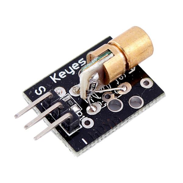
>| 6 | Temperature sensor NTC (KY013) | 
>| 7 | Pico Display Pack | 
>| 8 | Breadboard wires (female-male) | 
>| 9 | Breadboard wires (male-male), soft | 
>| 10 | Female header connector 2.54mm 2x20 pin | 
>| 11 | USB cable A-male to microB-male 0.5m | 
>| 12 | Adapter cable USB A-female to microB-male | 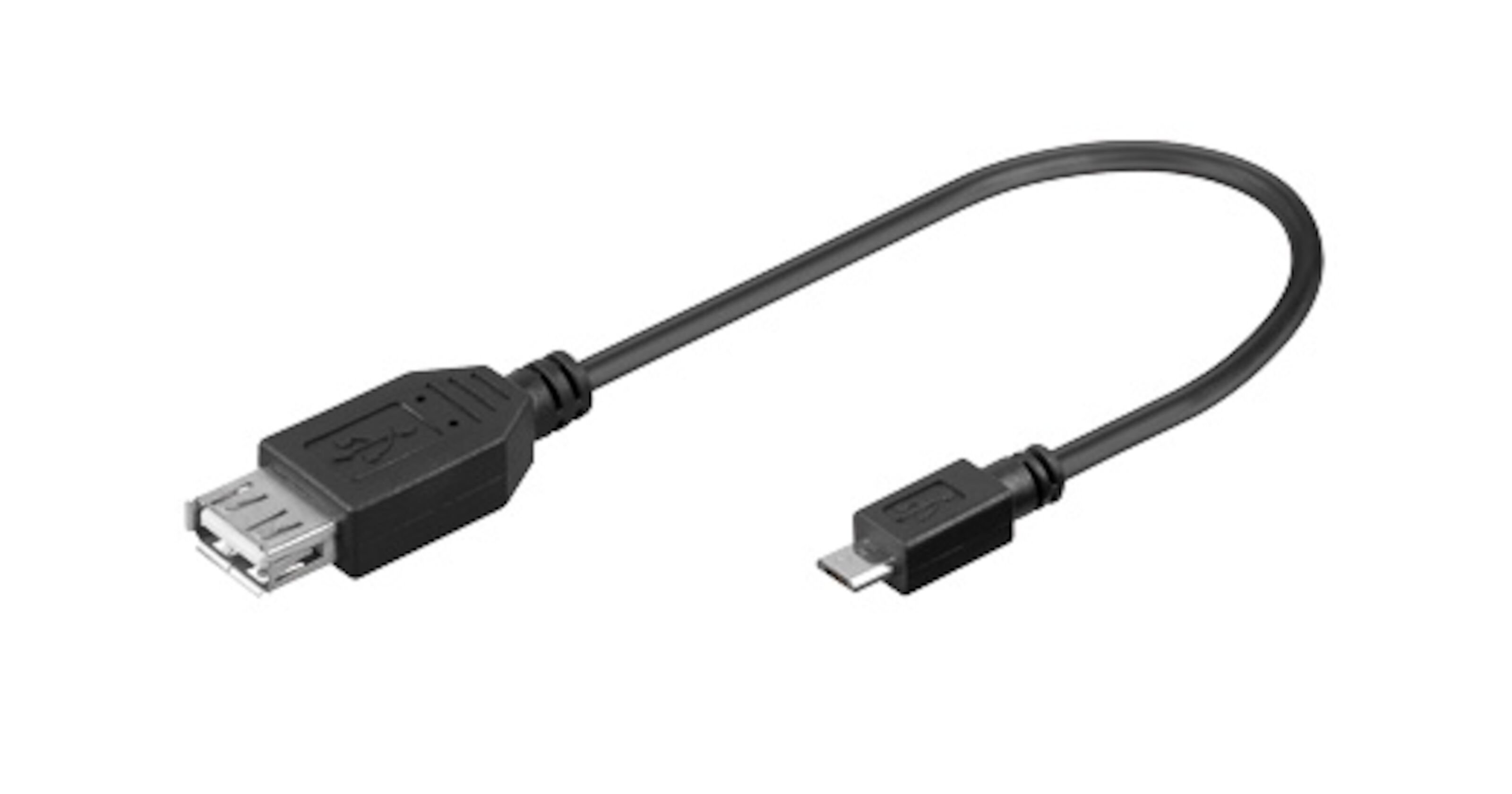
>| 13 | Raspberry Pi Power Supply | 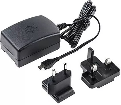
>| 14 | Soldering station 48W VTSS4/AP-2 | 
>| 15 | Solder wire 1.00 mm lead free 12.5g | 
>| 16 | 32GB SanDisk Ultra microSDHC Class 10 UHS-I 98MB/s A1 | 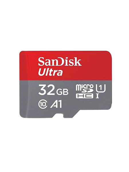
>| 17 | Memory card reader for Micro-SD card | 
>| 18 | Male header 2.54mm 2x40p side-entry breakable | 
### [](#Computer-setup "Computer-setup")Computer setup
**Prerequisites**
For this project I use a laptop with Windows 10. If you use a different operating system on your computer, the procedure for the installations may be different. Since I travel a lot while writing this tutorial, I will use examples where I use a local hot-spot on an android phone to access WiFi (This is also useful if you want to take your project with you somewhere where there is no WiFi.) If you already know that you will use your home router, you can choose to skip the step of activating a mobile hotspot.
Here you will find information on some things you need to do and how to install the required software:
+ [Activate mobile hotspot (Android)](#Hotspot)
+ [Install PuTTY](#PuTTY)
+ [Install Raspberry Pi Imager](#RPI-Imager)
- [Install Raspberry Pi OS Lite on SD card](#RPI-OS)
- [Test Raspberry Pi Zero W](#RPIZero-W-Test)
+ [Install firmware on Raspberry Pi Pico](#Firmware)
+ [Visual Studio code (VSCode) - IDE](#IDE)
- [Node.js](#Node.js)
- [Pico-Go](#Pico-Go)
#### [](#Hotspot "Hotspot")Hotspot
If you intend to take the project with you out of reach of your home network, it can be convenient to set up a temporary WLAN by using the Mobile Hotspot functionality on your phone.
In this tutorial, Mobile Hotspot will be used. If you use your home network, you can log in to your router instead. I will use **WLAN** as SSID and **YourSecretPassword!** as a password. Connect your laptop to this network.
#### [](#PuTTY "PuTTY")PuTTY
In this project we will do a headless setup with a Raspberry Pi Zero W (which has built-in WiFi) . This means that the RPI Zero W will have no mouse, keyboard or display. We will instead use the cryptographic network protocol SSH (Secure Shell) to securely and efficiently access the command line of the Raspberry Pi Zero W (from our computer) over our Mobile Hotspot/WiFi network. To be able to do this, we can use the free and open-source terminal emulator PuTTY.
Watch this video to see how to download, install and use PuTTY on your Windows machine.
{%youtube umFEuHWJW3w %}
Download and install [PuTTY](https://www.putty.org/)
#### [](#RPI-Imager "RPI-Imager")RPI-Imager
To be able to use Raspberry Pi Zero W, we need to download Raspberry Pi Imager and then install an operating system on the micro SD card.
Download and install [Raspberry Pi Imager](https://www.raspberrypi.org/software/)
##### [](#RPI-OS "RPI-OS")RPI-OS
After you have downloaded and installed Raspberry Pi Imager, you can watch this clip to see what the installation of Raspberry Pi OS on a micro SD card might look like. Wait to do the actual installation because we will do it slightly differently than in the clip.
{%youtube ntaXWS8Lk34 %}
1. Insert the SD card into the memory card reader. Insert the memory card reader into a USB socket in your laptop.
2. Start Raspberry Pi Imager.
3. Choose the Raspberry Pi OS Lite (32-bit) operating system
5. When you get to Step 2.5 (shown in the video above), press CTRL + SHIFT + X (Advanced options). To log in via SSH using PuTTY, I will use **pi** (default) as username and **YourPiPassword!** as a password. (You choose your own password). Fill in the values as shown below. For WiFi, enter the SSID (**WLAN**) and password (**YourSecretPassword!**) that you used for the mobile hotspot. Save and continue.


5. Choose your SD card (Storage)
6. Start the installation and wait until the installation is complete. Then remove your SD card reader from your laptop and remove the SD card from the card reader. Carefully insert the SD card into your Raspberry Pi Zero W.
##### [](RPIZero-W-Test "RPIZero-W-Test")RPIZero-W-Test
Now we will test and see if you can log in to your Raspberry Pi Zero W via PuTTy.
1. If you have not already inserted the SD card in your Raspberry Pi Zero W, do so.
2. Connect a power source (charger or powebank) to the micro-USB port marked **PWR** on your RPI Zero W. The green LED should start flashing. Let it boot. It may take a few minutes the first time.
3. Check your mobile hotspot on your phone. After a while, you should be able to see *raspberrypi* under *Connected devices*. Click *raspberrypi* to see its private IP address (My RPI has been assigned the IP address 192.168.43.19. Use the one assigned to your RPI Zero W). Save the IP address. You need it to log in to your RPI Zero W via PuTTY.

4. Open PuTTY on your computer and enter the IP address (Make sure port 22 and SSH are selected). Click "Open". You are now connected to your RPI Zero W.

5. You will now be asked to enter the username and password for your Raspberry PI Zero W (the username is **pi** and the password I chose was **YourPiPassword!**). If you have filled in the correct information, you will now have access to the terminal on your RPI Zero W. You can remain logged in or log in again later when you need to enter the code (shell script) needed on RPI Zero W.


You also need to disable TTY over serial communication on your Raspberry Pi Zero W in order for it to communicate via USB with Pico 2. Do the following:
> 1. Run sudo raspi-config to start the Raspberry Pi configuration utility
> 2. Select 5 Interface Options
> 3. Select P6 Serial Options
> 4. Select No when asked Would you like a login shell to be accessible over serial?
> 5. Select Yes when asked Would you like the serial port hardware to be enabled?
> 6. Select OK
> 7. Select Finish and select Yes to reboot when prompted
>
>**Source:** [raspi-serial](https://www.npmjs.com/package/raspi-serial)
If you want to update and secure your Raspberry Pi Zero W, you can read more about it in the links below.
[Updating and upgrading Raspberry Pi OS](https://www.raspberrypi.org/documentation/raspbian/updating.md)
[Securing your Raspberry Pi](https://www.raspberrypi.org/documentation/configuration/security.md)
#### [](#Firmware "Firmware")Firmware
Download firmware for Pico 1 and Pico 2.
[Pico 1 uf2](https://github.com/pimoroni/pimoroni-pico/releases/download/v0.2.3/pimoroni-pico-v0.2.3-micropython-v1.16.uf2) (Pimoroni firmware. Pimoroni is the manufacturer of the display and it requires a custom firmware.)
[Pico 2 uf2](https://www.raspberrypi.org/documentation/rp2040/getting-started/static/fec949af3d02572823529a1b8c1140a7/picoprobe.uf2) (Raspberry Pi firmware)
#### [](#IDE "IDE")IDE
In order to be able to more easily inspect and transfer code to the two microcontrollers, we will use an integrated development environment (IDE) called Visual Studio Code. Download and install [Visual Studio Code](https://code.visualstudio.com/).
##### [](#Node.js "Node.js")Node.js
Download and install the JavaScript runtime [Node.js](https://nodejs.org/)
##### [](#Pico-Go "Pico-Go")Pico-Go
Download and install the VSCode plugin [Pico-Go](https://marketplace.visualstudio.com/items?itemName=ChrisWood.pico-go)
You can follow [this tutorial](https://learn.pimoroni.com/tutorial/hel/getting-started-with-pico) to install firmware on your two Raspberry Pi Pico. This tutorial explains how to install firmware on **Pico 1** (the one with the display) but it works the same for **Pico 2**. But note that you should have already downloaded the separate .uf2 files for each Pico. Used the correct .uf2 file for the correct Pico, otherwise these will not work properly. Follow the guide to the section "Installing Thonny" but do not install Thonny (it is not necessary as we will use VSCode with Pico-Go instead).
### [](#Putting-everything-together "Putting-everything-together")Putting everything together
Solder pins according to the pictures and connect the Pico Display Pack to Pico 1.
Pico 1:
1. Connect positive pin on laser to pin 22. Connect ground on laser to pin 23.
2. Analog temperature sensor. Connect "-" pin to ground. S to ADC 1. Connect the center pin to 3.3 V.
3. Break the Male header (2.54mm 2x40p side-entry breakable) in the middle (so that it is 20 pins long = 2 x 20p). Attach a row from one side (1 x 20) to Pico 1 and the other side (2 x 20) to the bread board. This is done so that Pico 1 with Display Pack can stand on the side, which makes it easier to read the temperature while enabling the use of all pins on Pico 1.
Pico 2:
1. Fototransistor / Hear beat sensor. Cut off the led lamp. Connect "-" pin to ground. S to ADC 2. Connect the center pin to 3.3 V.
(Other connections are not used at this stage because code is missing.)
Connect the usb cable between the Pico 2 and the Raspberry Pi Zero W. Connect the Raspberry Pi Zero W and the Pico 1 to a separate 5v power supply.
Pico 1

Pico 2


### [](#Platform "Platform")Platform
For this project I have chosen to use cloud based platform ubidots.com (the free version). The reason I chose them was because they had a relatively clear description on their website of how to communicate via the MQTT protocol in JavaScript. It became my first choice because I had planned to make a Node.js (JavaScript) application on RPI Zero W that communicates both with Pico 2 via USB and with a platform via MQTT.
I have only had time to try a few functions on the platform because I spent most of the time experimenting with the hardware and code itself. But I can state that ubidots is user-friendly and it is quick to get started with that platform. I need to use Ubidots and other cloud providers (for IoT devices) more to be able to comment on which is the best option for me.
### [](#The-code "The-code")The code
To upload the code for Pico 1 and Pico 2:
Create a main.py (the filename is important) for each Pico and insert the code below into each file. Then connect one Pico at a time to your computer via USB and wait for it to be found by your computer (visible in the terminal in VSCode where it then says: "Connecting to COM3 ..." or another COM port depending on your computer).
When the Pico is connected, just click *Upload* on the blue line below the terminal. If you have done this with Pico 2, it should look something like in the picture down below. *Receiver initialized* means that the code is executed on Pico 2 and that it is ready to receive light signals from the laser on Pico 1.

**`main.py for Pico 1`**
```python
from machine import ADC
from machine import Pin
import picodisplay as display
import math
import utime
import json
# Temp sensor
adcTemp = ADC(1)
# Transmitter (Laser diode)
laser = Pin(22, Pin.OUT)
laser.value(False)
intv = 120
receiverStartDelay = int(0.5 * intv)
receiverDropTime = 6
# Display
buf = bytearray(display.get_width() * display.get_height() * 2)
display.init(buf)
display.set_backlight(1.0)
fontSize = 4
# Read and get the temperature by using the Steinhart-Hart equation
# Inspired by: https://arduinomodules.info/ky-013-analog-temperature-sensor-module/ 2021-08-02
def readTemp():
# Calculate resistance on the thermistor
thermistorR = math.log((1000/adcTemp.read_u16()) * (3300 - adcTemp.read_u16()))
# Temperature i Celcius
temperature = round(1 / (0.001129148 + (0.000234125 + (0.0000000876741 * thermistorR * thermistorR)) * thermistorR) - 273.15)
return temperature
# Convert a string to a list of binary 8-bit (byte) strings
def string2bits(s=''):
# Convert string to string of bits
bitStr = bin(int.from_bytes(s.encode(), 'big')).replace('0b', '0')
# Convert string och bits to list of binary 8-bit (byte) strings
byteList = [bitStr[i:i+8] for i in range(0, len(bitStr), 8)]
return byteList
# Transmit the bit by turning the laser on/off during the specified interval
def transmitBit(val):
laser.value(int(val))
utime.sleep_ms(intv)
# Send one start bit
def connect():
laser.value(1)
utime.sleep_ms(intv)
laser.value(0)
# Turn laser off
def disconnect():
laser.value(0)
# Send text message with laser
def send(message=''):
print("Sending data...")
connect()
# Convert the message (string) to a list of binary 8-bit (byte) strings
msgToBits = string2bits(message)
# Iterate each bit
for byte in msgToBits:
for bit in byte:
transmitBit(bit)
disconnect()
# Start the display
def initializeDisplay():
# Print "TEMP" with turquoise color
display.set_pen(0, 255, 255)
display.text("TEMP:", 10, 10, 130, fontSize)
# Print the temperature with white color
temp = str(readTemp()) + " 'C"
display.set_pen(255, 255, 255)
display.text(temp, 140, 10, 240, fontSize)
display.update()
# Update the display
def updateDisplay():
# Make the area where the old temperature was presented black (prevents flickering)
display.set_pen(0, 0, 0)
display.rectangle(140, 10, 100, 40)
display.rectangle(110, 50, 130, 40)
display.update()
# Print the temperature with white color
temp = str(readTemp()) + " 'C"
display.set_pen(255, 255, 255)
display.text(temp, 140, 10, 240, fontSize)
display.update()
# Clear the display (Make it black)
def clear():
display.set_pen(0, 0, 0)
display.clear()
display.update()
try:
# Start the display (Present temperature)
initializeDisplay()
# Loop every every ten seconds
while True:
# Update the temperature on the display
updateDisplay()
# Read the temperature and add it as a value to an object with the key "temp"
data = {"temp":"{0}".format(readTemp())}
# Convert it to a correct json format and then convert it to a json string
dataJSON = str(json.dumps(data))
# Print the json object in the terminal and then send it as 8 bit binary with the laser
print("data:", dataJSON)
send(dataJSON)
utime.sleep(10)
except KeyboardInterrupt:
clear()
disconnect()
```
---
**`main.py for Pico 2`**
```python
from machine import ADC
import sys
import utime
import _thread
# Thread variables
baton = _thread.allocate_lock()
# Receiver (Phototransistor/Modified heart beat sensor)
receiver = ADC(2)
baseVal = receiver.read_u16() # First reading
upperRangeVal = baseVal * 0.6 # Value to prevent triggering from daylight
intv = 120 # Interval. Flickering every 120 millisecond / 0.12 s
receiverStartDelay = int(0.15 * intv) # Delay to catch signal
receiverDropTime = 4 # Estimated phototranistor drop time
# List of recived characters and maximum bytes accepted/received signal
global charList # List of characters received
charList = []
global maximumBytes # Maximum number of bytes to listen for each during transmission
maximumBytes = 14
# Convert binary 8 bit to string char
def bits2string8bit(b=None):
return ''.join(chr(int(b, 2)))
# Handles the conversion from bits to char
def getMessage(bitStr, messageNoOfBytes):
global charList
# If it is the last byte
if messageNoOfBytes >= maximumBytes:
# Seal the other thread/core
baton.acquire()
# Convert binary 8 bit string to string character
byteChar = bits2string8bit(bitStr)
# Add the character to the character(string) list
charList.append(byteChar)
# Join all the characters in the list of chars (strings)
messageStr = ''.join(charList)
# Write the data to stdout (makes it visable for the RPI Zero W over USB)
sys.stdout.write(messageStr)
print()
# Reset the char list
charList = []
# Release the other thread/core
baton.release()
else:
# Convert binary 8 bit string to string character
byteChar = bits2string8bit(bitStr)
# Add the character to the character(string) list
charList.append(byteChar)
# Start the receiver
def initializeReceiver():
print("Receiver initialized")
while True:
# Read the value from the phototransistor
start = receiver.read_u16()
# If it is below the upper range value (Start bit received)
if start < upperRangeVal:
print("Message incoming...")
# Create a string for the bits
bitStr = ''
# Sleep until phototransistor returns to normal state
while receiver.read_u16() < upperRangeVal:
utime.sleep_ms(receiverDropTime)
# Delay to capture the bits
utime.sleep_ms(receiverStartDelay)
# Number of bytes received
messageNoOfBytes = 0
# Loop while receiving the signal
while True:
# Read the current value of the phototransistor
tempVal = receiver.read_u16()
utime.sleep_ms(intv)
# If it is below the upper range value = 1 = laser on
if tempVal < upperRangeVal:
bitStr = ''.join((bitStr,'1'))
# If it is above or equal to the upper range value = 0 = laser off
elif tempVal >= upperRangeVal:
bitStr = ''.join((bitStr,'0'))
# If 8 bits / 1 byte has been received
if len(bitStr) == 8:
# Increment the byte counter
messageNoOfBytes += 1
# Start a new thread to handle the conversion from byte to char
_thread.start_new_thread(getMessage, (bitStr, messageNoOfBytes))
# Reset the bit string
bitStr = ''
# If the maximum number of allowed bytes has been received
if messageNoOfBytes >= maximumBytes:
utime.sleep(1)
# Break signal receiving loop
break
else:
# Sleep time while there is no signal
utime.sleep_ms(intv)
try:
initializeReceiver()
except KeyboardInterrupt:
_thread.exit()
```
---
**`Shell script for Raspbery Pi Zero W`**
On your RPI Zero W (via PuTTy) you create a script by typing:
```bash
nano rpiZero.sh
```
Paste the code from the file below (copy the code and then right-click in the terminal and it will be pasted).
Important! Go down to the line about "MQTT auth variables". Change these (token and device) to your own that you receive after you have registered on ubidots.com.
```bash
// MQTT auth variables.
const token = '' // EDIT THIS
const device = '' // EDIT THIS
```
Save by pressing CTRL + X. Press Y, then press ENTER.
Change the permissions on the file so that it can run as a script:
```bash
chmod 755 rpiZero.sh
```
Run the script:
```bash
./rpiZero.sh
```
When the script has finished running and you have connected everything, you only need to run:
```bash
npm start
```
Now the application starts on your RPI Zero W and it now listens for messages coming from your Pico 2 (via USB) which in turn listens for messages via its phototransistor (which listens to the laser light transmitted from Pico 1). In the beginning, you may need to move around Pico 2 so that it ends up in such a position that it perceives the signal properly (the laser beam hits the right place on the phototransistor). Once you have done that, messages should appear in the terminal. If these messages (with temperature data) are in the correct format, these will be sent to Ubidots.
```bash
#!/bin/sh
# Update and upgrade
sudo apt update
sudo apt full-upgrade
# Create directory for the project
mkdir iot
cd iot
# Install Node.js and NPM
# Source: https://hassancorrigan.com/blog/install-nodejs-on-a-raspberry-pi-zero/ 2021-07-31
# *****************************************************************************************
# Download Node.js 14.17.4 LTS
wget https://unofficial-builds.nodejs.org/download/release/v14.17.4/node-v14.17.4-linux-armv6l.tar.xz
# Extract the file into a directory
tar xvfJ node-v14.17.4-linux-armv6l.tar.xz
# Copy the content of the directory to usr/local.
sudo cp -R node-v14.17.4-linux-armv6l/* /usr/local
# Clean up
rm -rf node-*
# *****************************************************************************************
# Create package.json
cat > package.json << EOF
{
"name": "pizerow",
"version": "1.0.0",
"description": "",
"main": "src/server.js",
"scripts": {
"start": "node src/server.js"
},
"author": "Fredrik L",
"license": "MIT",
"dependencies": {
"mqtt": "^4.2.8",
"serialport": "^9.2.0"
}
}
EOF
# Create server.js
mkdir src
cat > src/server.js << EOF
const SerialPort = require('serialport')
const mqtt = require('mqtt');
// MQTT auth variables.
const token = '' // EDIT THIS
const device = '' // EDIT THIS
// Connect to ubidots
var client = mqtt.connect('mqtt://industrial.api.ubidots.com', {username:token, password:""})
// RPI Zero W listening to RPI Pico over USB
const serPort = new SerialPort('/dev/ttyACM0', { baudRate: 115200 })
serPort.on('error', function(err) {
console.log('Error: ', err.message)
})
// When data is received via USB serial communication
serPort.on('data', function (data) {
// Print output in the terminal
picoData = (data.toString('utf8')).trim()
// Check if the data is valid JSON
if (checkData(picoData)) {
console.log('Data from Pico is JSON format. Sending data to Ubidots')
// If it is valid JSON - send it to Ubidots, using MQTT
sendData(picoData)
} else {
console.log('Data from Pico is NOT JSON format.')
}
// Always print recived message for better troubleshooting
console.log('RPI Pico: ', picoData)
})
// Check if the data is JSON
function checkData(data) {
// Check if it is a string
if (typeof data !== 'string') {
return false;
}
try {
// Try to parese the data to an object
let dataObj = JSON.parse(data);
console.log('DataObj: ', dataObj)
console.log('Data param: ', dataObj.temp)
// Check that the objects contains the key 'temp'
if ('temp' in dataObj) {
console.log('Has temp in obj')
// Check that the value is a number
let tempIsNumber = isNaN(dataObj.temp)
if (!tempIsNumber) {
console.log('Temp is number')
return true
} else {
console.log('Temp is not number')
return false
}
} else {
console.log('Has no temp in obj')
return false
}
} catch (error) {
return false;
}
}
// Send the data to Ubidots
function sendData(data) {
// Convert the string to correct json object format and then make it a string
let jsonData = JSON.stringify(JSON.parse(data))
// Publish the data on Ubidots
client.publish(`/v1.6/devices/${device}`, jsonData, {'qos': 1, 'retain': false},
function (error, response) {
console.log(response);
})
}
EOF
# Install packages
npm install
```
### [](#Transmitting-the-data--connectivity "Transmitting-the-data--connectivity")Transmitting the data / connectivity
In the pictures below (in the next section "Presenting the data") you can see how the data received on RPI Zero W (from Pico 2) is analyzed and if in the correct format it is sent to Ubidots via the MQTT protocol. I have not had time to test over any longer periods, but the code that is run (the pictures and the code that is attached) saves the data at Ubidots every 10 seconds. Maybe not so necessary but it worked well for experimental purposes during the final phase of the project.
In order for the temperature from the sensor to reach Ubidots, the following protocols are used:
1. Custom and simplified "unidirectional 8-bit binary LiFi" (flashing laser from Pico 1 to phototransistor at Pico 2).
2. Then Serial communication via USB from Pico 2 to Raspberry Pi Zero W.
3. Finally, the data is sent in json format using the MQTT protocol over WiFi from the Raspberry Pi Zero W to the mobile hotspot on the phone and then via the 4G / 5G network (IP) to Ubidots.
### [](#Presenting-the-data "Presenting-the-data")Presenting the data


The dashboard is simple with only one line chart. This is because I have not had time to try much of the various other functionalities, but it is enough as proof of concept. I have not been able to find how long Ubidots saves the data.
### [](#Finalizing-the-design "Finalizing-the-design")Finalizing the design
The project has been fun and very educational. I have had time to experiment with both Lopy FiPy and Raspberry Pi Pico during this project, which I have not done before. I have also gained a basic understanding of how to work with sensors. I also learned to use basic python. In the end, I got to try sending data by light and even though it was slow, it was fun to see how you can really connect many different devices.

* * *