# PocketNC - 5-Axis CNC Mill
**[Wiki Home](https://hackmd.io/@fablabedp/home)**
###### tags: `equipment` `CNC`
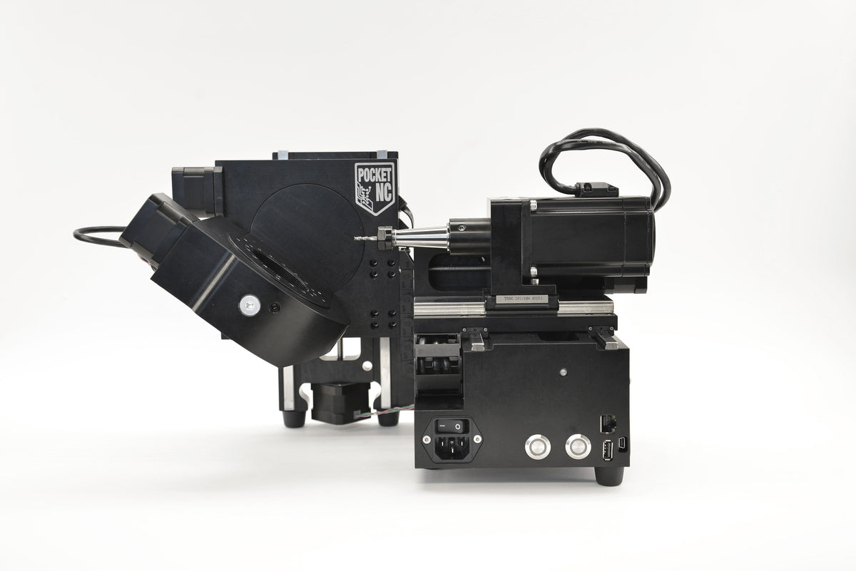
**Pocket NC V2-10 - 5-Axis CNC Mill**
## References
[PocketNC V2 Legacy Resources](https://pentamachine.atlassian.net/wiki/spaces/PNFUR/pages/1728217119/V2+Legacy+Resources)
[PocketNC V2-10 Speeds and Feeds](https://pentamachine.atlassian.net/wiki/spaces/PNFUR/pages/370507817/V2-10+Speeds+and+Feeds)
[PocketNC Gcode Simulator](https://sim.pocketnc.com/)
[Generic Gcode Simulator](https://ncviewer.com/)
## Technical Specs


### Materials
> OEM tested materials
>
> - G5 titanium
> - 6061 aluminum
> - 303 stainless
> - machinable wax
> - acetal
## Edge finding
B Axis offset
Default offset of 0.885 in.
*insert* measured offset.
Turn on and home all axis
Measure tool and stock
Measure diameter of the edge finder tip (OEM is 0.200 in).
Measure your stock (material) and ajust the model to match the size.
Measure Tool Length Offset
Measure the machining tool length offset of the tools you will be using for machining the part.
When measuring tool length offsets is complete, load the edge finding tool holder into the spindle and installit. You do not need to measure the tool length offset of the edge finder.
Don't forget the dowel pins if you choose to install the vise
Collet order:
1 - Bottom tapered nut
2 - Collet
3 - Top tapered nut
Measure X offset:
First of all, measure the X offset. Use the manual controls to move the spindle alongside the stock on the outside (opposite from the A table side) of the stock. The edge finding tool should be parallel to the X face of the stock.
Bump the wobbler on the edge finder slightly so that it is not concentric with the shank. Turn on the spindle using the MIDI command G0 G90 M5 S1000. [Do not exceed the maximum speed for which the edge finder is rated.]
EDGE FINDER MAX. SPEED 2.000 rpm
Bumping the wobbler, with a finger or other object, while the spindle is turning is not recommended.
Only adjust the wobbler position when the spindle is off.
Move the tool toward the face. Decrease the step size to 0.001 inches or less as you get close to the part. As the wobbler starts to touch the face it will start to spin more concentrically with the shank of the edge finder. Keep moving the edge finder toward the part until the wobbler spins concentrically with the shaft of the edge finder. Continue to move the edge finder closer to the part until you see the wobbler suddenly “jump” to a new position that is no longer concentric with the shank of the edge finder.
The tip will deflect when it touches the part.
Look at the Digital Readout (DRO) and record the X position.
Type “G0 G90 M5” into the MDI window to stop the spindle.
The offset is the X distance displayed in DRO minus half of the edge finder tip diameter. The calculation for the X offset is: (absolute value of measured X distance) - (½ edge finder tip diameter) = X offset.
Measure Y offset:
Move the spindle so that the edge finder is above the stock. The tool should be parallel to the Y face of the stock.
Bump the wobbler on the edge finder slightly so that it is not concentric with the shank.
Turn on the spindle. [Do not exceed the maximum speed for which the edge finder is rated.]
Move the tool toward the face. Decrease the step size to 0.001 inches or less as you get close to the part. As the wobbler starts to touch the face it will start to spin more concentrically with the shank of the edge finder.
The tip will deflect when it touches the part.
Look at the Digital Readout (DRO) and record the Y position.
Type “G0 G90 M5” into the MDI window to stop the spindle.
The offset is the Y distance displayed in the DRO, minus half of the tool diameter. The calculation for the Y offset is: (Y distance) - (½ Edge Finder Tip Diameter) = Y offset.
Eg. Y offset = 1.2552 - 0.200/2 = 1.1552 inches.
Compare this measured Y offset with the distance between the origin and the Y face in Fusion. If they do not match, move the part in Fusion until the measured Y offset and the model Y offset match.
[Do not adjust the size of the stock in CAD. Instead use the move commands to adjust its location.]
If the distance measured from the machine origin to the Y surface and the model value are significantly different before adjustment, and you have measured your stock and verified that the model dimensions match the physical dimensions, it means that your machine origin in your model may be in the wrong location. Double check before proceeding.
Once the digital origin and the physical origin are coincident, generate and post-process the toolpaths.
[Do not move the stock after it has been located through the edge finding process. If the stock is moved, the edge finding process will have to be repeated.]
[] = disclaimers
## Rotated Work Offsets Tutorial
Pocket NC’s Rotated Work Offsets feature allows users to set a work coordinate system (WCS) origin that is relative to a point on a part or its stock, instead of a point that is relative to the machine (typically the center of rotation).
This allows the stock to be loaded onto the machine differently than it is modeled in the CAM workspace while maintaining the ability to perform positional 5 axis tool paths, otherwise known as 3+2 machining.
[This tutorial is made for Fusion 360 other CAM software might work similarly.]
Step 1: CAM Setup
Create a new setup
orient the part the way it will sit on the machine when the A and B axes are at 0 degrees.
use “Select Z axis/plane & X axis” to orient the WCS the way the machine’s axes are oriented in relation to front facing the machine.
Pick your preferred origin point for the WCS.
Below, the corner of the stock that is closest to the spindle and the front of the machine has been chosen for ease of access.
move to the “Stock” tab.
begin defining your stock and its position relative to the part.
Lastly, move to the “Post Process” Tab.
In this example, we are using WCS offset 1 because we want to use the G54 code to define our work offsets on the machine.
You may use any number from 1 to 8 here, just make sure you are aware of what G5x the number corresponds to.
Step 2: Tool Path Application
Now that the setup is configured correctly, tool paths can be applied.
Tool paths and machining operations can be configured using the same method used when programming around center of rotation.
The only difference will be where the WCS is displayed relative to the model, but [as long as it is oriented the way it needs to be to cut the desired feature], there will be no effect on the final tool path.
Step 3: Post Processing
After creating all the tool paths and the part ready to cut, it is time to post process them into g-code.
Begin by right clicking on the setup that was created in step one, in this example we have named it “Setup 1”, and then select “Post Process”.
Adjust your post processor window following the settings shown below.
The program number and program comment can be whatever you would like.
In the "Properties" section, in the WCS parameter choose a virgin WCS meaning that it can't be already in use.
You can check if they are assigned in the Post Processor tab of of your program’s setup.
Next, locate the property titled “Machine Model” and select the model of Pocket NC machine that this program will be run on.
Finally, post process the g-code by clicking “OK” or “Post”.
It is good practice to keep the .ngc file extension on the file name.
Step 4: Machine Set Up
After g-code generation, the machine has to be set up. The majority of this process is the same as setting the machine up to cut a part that is programmed around the center of rotation:
-Turn on the machine and home its axes.
-Install necessary fixtures.
-Install and measure the tools that will be used.
-Install the stock material, locating it on the fixture in the orientation that was planned at the start of the CAM programming.
Step 5: Setting Work Offsets
*link to paper method*
Step 6: Simulate and Run
[RWO (Rotated Work Offsets) Tutorial - User Resources - Confluence](https://pentamachine.atlassian.net/wiki/spaces/PNFUR/pages/1249378352/RWO+Rotated+Work+Offsets+Tutorial)
## Setting Work Offsets (Paper Method):
This is a manual intervention step where the machine is told what point all of the g-code coordinates originate from.
There are several ways to perform this process but in this example we are going to use the simple touch-off/paper method.
Install the tool (usually an endmill) you wish to use for this process.
It is recommended that the tool has three or more flutes for better functioning.
In the source example they use a 1/8” single-flute endmill turned inwards the tool holder.
Measure the inserted tool.
If the tool being used to set work offsets is not a tool that will be used in the program you will need to pick a empty tool number slot.
Setting Z Work Offset
Take advantage of the jog control to aproach the tool to the right side of the stock inside it's front face.
For the DRO readout to be accurate we need to call out the TLO "G54 G43 Hx" through the command input.
Note: The Gcode “H” value must match the tool number used for the touch-off tool.
Making use of the 0.1 precision bring the tool closer to the stock.
[Be careful not to go too far and collide the tool with the stock.]
Once it's close enough increase the precision by using the 0.001 scale and with the aid of the calibration paper move the tool until the paper has been pinched.
Note: Feel free to go as far as 0.0001 scale for greater precision.
in the interface go to "Tooling" and in the “Work Offsets" tab click on the input box in the Z row and G54 column.
Select “Zero DRO”.
Note: You can select “Set DRO to a Value” and then entering the thickness of the paper and the new DRO value has a more accurate offset.
Setting the X Work Offset
Take advantage of the jog control to aproach the tool in front of the stock and just below the top of the stock.
Making use of the 0.1 precision bring the tool closer to the stock.
[Be careful not to go too far and collide the tool with the stock.]
Once it's close enough increase the precision by using the 0.001 scale and with the aid of the calibration paper move the tool until the paper has been pinched.
Note: Feel free to go as far as 0.0001 scale for greater precision.
in the interface go to "Tooling" and in the “Work Offsets" tab click on the input box in the Z row and G54 column.
Select “Set DRO to a Value”.
You will need to insert the negative of the radius of the choosen tool, meaning that value is how far the center of the tool is offset from the face of the stock in the negative direction.
Note: Include the thickness of the paper in the new DRO value for a more accurate offset.
Setting Y Work Offset
Take advantage of the jog control to aproach the tool on top of the stock near the front corner of the stock.
Making use of the 0.1 precision bring the tool closer to the stock.
[Be careful not to go too far and collide the tool with the stock.]
Once it's close enough increase the precision by using the 0.001 scale and with the aid of the calibration paper move the tool until the paper has been pinched.
Note: Feel free to go as far as 0.0001 scale for greater precision.
in the interface go to "Tooling" and in the “Work Offsets" tab click on the input box in the Z row and G54 column.
Select “Set DRO to a Value”.
You will need to insert the negative of the radius of the choosen tool, meaning that value is how far the center of the tool is offset from the face of the stock in the negative direction.
Note: Include the thickness of the paper in the new DRO value for a more accurate offset.
[RWO (Rotated Work Offsets) Tutorial - User Resources - Confluence](https://pentamachine.atlassian.net/wiki/spaces/PNFUR/pages/1249378352/RWO+Rotated+Work+Offsets+Tutorial)
## Throubleshooting
- Doesn't operate
- ...
- Errors during operation
- ...
- Unexpect Program Operation
- I can't open a file ...
- The included software doesn't function ...
- If an error mensage appears ...
## G and M Code
G0 G90 M5 - Stop the sindle
G0 G90 M5 S1000 - Turn spindle on (1000 rpm)
G5X - Work offsets
G54 G43 Hx - TLO (H value is the tool number)