# MODELA - Milling Machine
**[Wiki Home](https://hackmd.io/@fablabedp/home)**
###### tags: `equipment` `CNC`
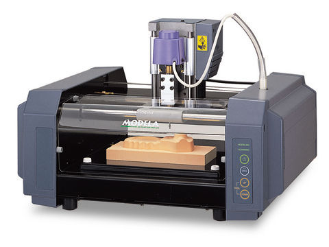
**Roland MODELA MDX-20 - Milling Machine**
https://www.rolanddga.com/support/products/milling/modela-mdx-20-3d-milling-machine
### Technical Specs
- Build Area: 203.2 x 152.4 x 62.4mm
- Max Weight: 1000 g
- Milling
- Chuck: 6 or 1/8in OEM
- Sindle motor: 10W
- RPM: 6500
- Accepted material: Wood, Plaster, Resin, Chemical Wood, Aluminum (A5052), Brass
- Scanning
- Sensor: Piezoeletric
- Method: Probing Contact, mesh
- Speed: 4 - 15mm/sec
- Interface
- Standard: RS-232C
- Baudrate: 9600 bps
- Data Bits: 8 bits
## How to setup Modela Player
[Do not use modela player for PCB]
Modela has a dedicated software for the Roland Modela MDX-20 in which you have access to the materials available and you can define your tool arsenal.
The software also allows you to prepare your model to be machined.
Step 1: Open Modela Player
Step 2: Select the machine
Go to [File] and click on [Select machine...] to appear a new window
Define the following:
Model name: MDX-20
Command set: RML-1
Spindle Unit: Standard
Printer Name: Find "Roland MODELA MDX-20"
Step 3: Go to [File] and select [Open]
It will open a File Explorer window in which you will select the model to input in the player.
Modela Player allows the following formats: .mpj, .dxf, .igs, .mdj .
Step 4: Go to [Set] and select [Model]
It is now necessary to define the model orientation and its origin.
In the Size and Orientation tap make sure of the following:
Model Size: Length
Check if the model dimensions are accurate and keep the ratio.
If the model wasn’t modeled in the way that respects the coordinates, make use of the Orientation area to define the top surface by clicking on the dot that shows the right position in relation to the X/Y axis.
Go to the [Origin] tab
You can see that in a simple and clear way it allows to select the model origin just by clicking the dot , to define the origin.
It is recommended to select the lower left corner.
Click [Ok]
Step 5: Make sure that the tools needed for the job are defined in the [Add/Remove Tool] option.
If the tools selected for the task aren't already in the library please insert them as specified below:
-Go to [Options] and select [Add/Remove Tool] a window will pop up.
-Select [New].
A new tool slot will appear allowing to select the parameters according to the specs of the tool.
-Give your tool a name keeping the following pattern: *tool diameter* *type of tool tip* eg: 1mm Square
-Define the tool material.
Typically the material is HSS (High Speed Steel).
The CC (cemented carbide) is usually a special material and more expensive.
- Set the flute diameter.
- Click on [Cutting Parameters...]
- Select the material through clicking on the list in front of the material.
- Click on [Set Parameters]
- Double check the cutting parameters and feel free to adjust according to the material of choice.
It is recommended to leave them asdefault.
- Officialize the parameters by clicking on "Register"
Now your tool is ready to use?
Step 6: Defining a new process
This will allow you to choose the order and which processes you would like to make.
It is strongly recommended to respect the following order: Surfacing -> Roughing -> Drilling* -> Finishing**
* -The rilling depends on the part it can be ignored if not needed.
** - It is recommended to make a finishing process only after the part as been machined to that stage.
Select the New process button with a ladder figure.
A window will appear with the following options:
o Surfacing
o Roughing
o Finishing
o Drilling
As the processes is very similar, setup-wise the following will be a generic followthrough in that new window.
- Choose the type of process
- Select the cutting surface
- Choose the tool for the process
- Select the area and depth
- Choose the type of tool path to create
- Select the cutting parameters
- Enter a name for the process
### Throubleshooting
- Doesn't operate:
Is the STANDBY key on?
Press the STANDBY key.
Has operation not been paused by pressing the VIEW key (lighting up the VIEW LED)?
Press the VIEW key to cancel the View state.
Are the cables connected correctly?
Check MODELA outputs to make sure they are connected correctly.
Is the cable for the connection with the computer suited to the MODELA and the computer?
For the cable, use a ptionally aveilable serial cable (such as XY-RS-34). A straight serial cable suchb as is commonly used to connect a modem cannot be used.
Are the settings for the computer and the software correct?
Check the following and make the correct settings.
Data output port :Port connected to any one of COM1 throught COM4
Communication parameters:Bit rate of 9600, no parity, one data bit, stop bit 8, and hardware handshaking
Select output device :MDX-15 or MDX-20
- Modeling mode LED/Scanning LED flashing (10x sec):
Was the power switched on in the correct sequence?
First turn on the computer, then turn on MODELA.
This indicates a communications error.
Switch off the power, then check the cable connections and the port setting for the driver.
Was the computer restarted?
When the computer has been restarted, switch the power to the MODELA off, wait a few seconds, then switch it back on.
- All LEDs fashing slowly:
Has the power cord come loose from the tool?
Switch off power and connect the cords to the jacks.
- Errors during printing
- Speed drops during cutting
When cutting a workpiece of uneven hardness, such as wood, the MODELA may slow down automatically (to a minimum speed of 0.1mm). Once the MODELA has gone beyond the hard area, cutting continues at normal speed.
- The standby LED is flashing slowly
The workpiece cannot be cut, even when the speed is reduced. Switch the power off and back on.
Make sure the cutting tool being used is appropriate for the hardness of the workpiece in use. Modify the software settings to cut the workpiece a little at a time.
- Actual tool moviment diffent than data
If an attempt is made to cut more deeply then the rage of moviment for the MODELA allows, the tool automaticallyt rises to te uppermost point.
Check to make sure that the erpt settings in the cutting data are not too dseep, and that the tool extending from te sinde unit is not too short.
- Correct cutting is impossible
Are the tool, spindle, and workpiece all installed and loaded securely?
Rethighten ghe setting screw for the tool and the mounting screws for the spindle.
- Unusual noise is heard from the spindle
The spindle unit is a consumebla part. Replace with a new spindle after 700 hours of use.
- The sindle motor does not run
The sindle motor is a consumable part. Replace with a new spindle motor after 700 hours of use.
- The VIEW LED is flashing slowly (1 sec. interval)
Is the fornt cover emovet?
Install the front cover.
When a sensor unit is installed, The VIEW LED does not flash.
- Scanning LEDs flashing twice repeatedly:
- Unexpect Program Operation
- I can't open a file
- The included software doesn't function
- If an error mensage appears
_All units in milimeters_
 Sign in with Wallet
Connect another wallet
Sign in with Wallet
Connect another wallet