<font face="Dejavu Sans"/>
# ItC Week 4~6 - Sequential Logic
###### tags: `Intro_to_Comp`
- ## Some Examples
- Finite State Machine
- Markov Model
- Markov model is one kind
- Hidden Markov Model
- RNN & LSTM
- Sequence to Sequence Model
- ## Introduction
- Some definitions
- state : all the necessary information to know a circuit's futrue behavior
- latches and flip-flops : store one bit of state
- synchronous sequential circuits : combinational logic + flip-flops
- ## Latches and Flip-Flops
- Bistable Circuit
- 
- store 1 bit of state
- but there are no input to control the state
- SR(Set/Reset) Latch
- 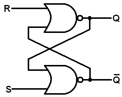
- must avoid $S=R=1$ (cause invalid case like $Q = \overline Q$)
- D Latch
- 
- essentialy it is just a modified version of SR latch
- avoids SR latch's problem
- D Flip-flop
- 
- synchronize with clock at the start of 1
- only allow $D$ go through when clock go from 0 to 1 (a.k.a."*edge triggered*")
- D Latch v.s. D Flip-flop
- 
- Be careful with latency in circuits!
- Enabled Flip-flop
- 
- A multiplexer + A D Flip-Flop
- The enable input decide when $D$ should pass through
- Resettable Flip-flop
- If $Reset$ is 1, Q is forced to be 0
- Else, it behaves like a normal D flip-flop
- Settable Flip-flop
- It's like the resettable flip-flop, but is forcing 1
- Memory Register
- Register Implementation
- ## Synchronous Logic Design
- Sequential circuits
- all circuits that are not combinational
- System synchronized to the clock
- Rules
- each element is either a regster or a combinational circuit
- contains at least 1 register
- all element recieve the same clock(no latency)
- ## Finite States Machine
- Next state determined by input and current state
- Moore FSM
- 
- outputs depend on only current state
- Mealy FSM
- 
- outputs depend on current state ***and*** inputs
- **Implementation : Traffic Light**
- **Implementation : Snail**
- Moore Machine Approach
- Mealy Machine Approach
- Time Diagram : Moore v.s. Mealy
- When sychronized to the clock, their outputs might not happen at the same time.
- Because Moore's output happens when entering the state, it will be a bit slower than Mealy's output, which happens when recieve input.
{%hackmd BJrTq20hE %}
<!-- <style>
/* h1 {
font-family: 'Oswald', sans-serif;
} */
/* h1{
animation: rainbow 2.5s linear;
animation-iteration-count: infinite;
} */
h1:hover{
animation: rainbow 2.5s linear;
animation-iteration-count: infinite;
}
img.ui-avatar{
animation: spin 1s linear;
animation-iteration-count: infinite;
}
/* img{
transition: all 1s;
}
img:hover{
animation: zoom 1s;
animation-fill-mode: forwards;
} */
@keyframes rainbow{
100%,0%{
color: rgb(255,0,0);
}
8%{
color: rgb(255,127,0);
}
16%{
color: rgb(255,255,0);
}
25%{
color: rgb(127,255,0);
}
33%{
color: rgb(0,255,0);
}
41%{
color: rgb(0,255,127);
}
50%{
color: rgb(0,255,255);
}
58%{
color: rgb(0,127,255);
}
66%{
color: rgb(0,0,255);
}
75%{
color: rgb(127,0,255);
}
83%{
color: rgb(255,0,255);
}
91%{
color: rgb(255,0,127);
}
}
@keyframes boing {
15%, 40%, 75%, 100% {
transform-origin: center center;
}
15% {
transform: scale(1.2, 1.1);
}
40% {
transform: scale(0.95, 0.95);
}
75% {
transform: scale(1.05, 1);
}
100% {
transform: scale(1, 1);
}
}
@keyframes spin {
from {
transform:rotate(0deg);
}
to {
transform:rotate(360deg);
}
}
@keyframes zoom {
100% {
transform: scale(2,2)
}
}
</style> -->
 Sign in with Wallet
Connect another wallet
Sign in with Wallet
Connect another wallet