[](#Template "Template")I built a remotely monitored robot vacuum cleaner out of plywood - and it sucks!
================================
*Made by Anna Pohl Lundgren (ap223vc)*
**Estimated time:** 30 hours
**Estimated cost:** $190
In this tutorial I will describe the process of building a remotely monitored robot vacuum cleaner prototype!

The robot uses a simple algorithm to move randomly across the floor, and sends data to the Pybytes platform. Unfortunately, it does not work very well, though (luckily) in order to not disappoint myself, I always considered good functionality a bonus! In this tutorial, I will also cover the areas I'm still working on in my quest of making it actually useful.
## [](#Objective "Objective")Objective
---
I chose this project to put my first three years of engineering studies to the test, to learn laser cutting and building stuff, and because I hate cleaning. Also, it's kinda cool, right? The objectives of the project are:
1. Experience the product development process!
2. Getting the hang of using electronics to solve problem
3. Using an IoT platform to visualize data
4. Maybe, *maybe* (maybe!) get some help with the cleaning
## [](#Material "Material")Material
---
**Let's begin by listing some handy (and sometimes needed) tools!**
- [ ] **Laser cutter** - Yeah... After a year with a pandemic, the money I didn't spend on social activities was enough to buy me one. It's probably possible to simplify the design or achieve it with other wood crafting tools if you're crafty. I have an Atomstack A5 30W laser engraver and cutter (which has a *laser power* of up to 5.5W, not 30W). It's a cheap one, for being a laser cutter. Your local makerspace likely has a better one you could borrow, given you are willing to learn how to use one!
- [ ] **Cutting blade knife** - There are multiple times where I found I didn't have the right tool at hand, but managed to solve the problem with a simple cutting blade knife.
- [ ] **Drill** - I used a screwdriver with drilling bits, which proved invaluable a lot of times
- [ ] **Sandpaper** - Yea, it's the shit.
- [ ] **Multimeter** - I consider this a must have for trouble shooting - and a cheap one is fine. And being able to double check the polarity of power supplies saves both nerves and electrical components!
- [ ] **Soldering station** - Sometimes, sensors and microcontrollers come without pin headers. It sucks, but not as hard if you have a soldering station. If you want to make your project permanent, a breadboard usually won't cut it, and soldering the components onto a prototype board is more robust.
- [ ] **Adjustable DC power supply** - Even if the device will run on a battery, this is extremely useful in the development process.
- [ ] **Breadboard** - Being able to quickly prototype and test a circuit is very time saving.
### Building materials
* **Plywood**: The chassi is mainly built out of 3 mm thick birch plywood, which is about the thickness one can expect a 5.5W diode laser (such as mine) will be able to cut. For the lid on top of the fan, which is purely for aesthetic purposes, I used 1.5 mm plywood.
* **Cork sheet**: Used for the curved front, and holding the lid in place. Found [this cork deskpad](https://www.ikea.com/se/sv/p/susig-skrivunderlaegg-kork-90457486/) on IKEA, which worked well.
* **Screws and nuts**: I mainly used M3 and M4 screws and nuts, of some different lengths. These kind of things are always good to have a little of everything, in order to see what fits.
* **Wood glue**: Most parts of the chassi are glued together.
* **Caster wheel**: The passive (non-powered) front wheel, to keep the robot steady.
I also got some wooden rest material from friends and family, which came in handy sometimes.
### Electrical components
Listing all the types of wires and adapters I used and why during the project would be tedious, and probably misleading. As a wise person once said:
> "The wire you need is always one that you don't have"
Yes, that is a fake quote. I'm not very wise. A general recommendation is to at least begin with male-to-male, male-to-female and female-to-female jumper cables, and to make sure you have some way of getting power onto a breadboard. When you buy a new component, look up the connectors and see if they need special cables, or maybe some spicy screw to be mounted properly. It's okay to buy things when you realise you need it, but it's always frustrating being one Deans-T connector away from plugging your battery into the circuit.
- **Microcontroller**: I used a Pycom LoPy4 device as seen below. It is a great IoT device with several bands of connectivity (wifi, Bluetooth, LoRa, Sigfox...), but for this project it may actually be a bit overkill. A great feature though is being able to (relatively painlessly) connect the device to Pybytes, which makes the monitoring part easier. The programming language is Micropython, which is relatively simple to learn. If I wasn't going to connect the device to the internet, I would probably use a [Raspberry Pi Pico](https://www.electrokit.com/produkt/raspberry-pi-pico/) instead - it's *a lot* cheaper and still provides all the required pins.  LoPy device ([Pycom.io](http://Pycom.io))
- **Accelerometer, gyroscope and temperature sensor module, MPU6050**: Used to detect wall collisions. Accessed via I2C, supply voltage 3.3-5V. Note that the pins don't always come pre-soldered.
- **Fan**: I use a computer fan to (try to...) suck up the dust. The model used is a white 12V Cooler Master SickleFlow 120, which is a 4 pin PWM-fan with 6 addressable RGB LED:s as an added bonus. To be honest, it's not doing a great job at the moment, but with some further modifications of the design it might be good enough in the future. 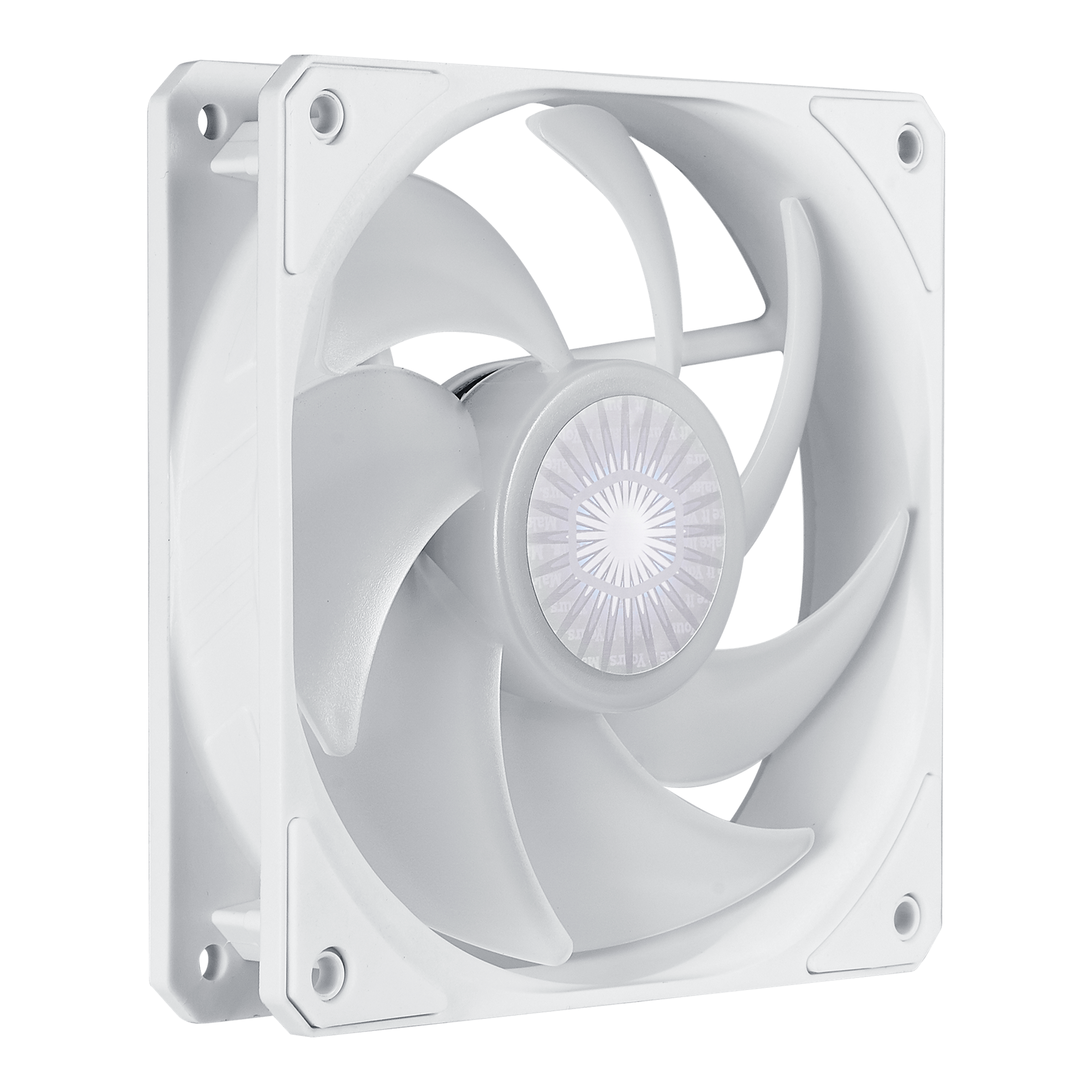 Computer fan ([coolermaster.com](https://www.coolermaster.com/catalog/coolers/case-fan/sickleflow-120-argb-white-edition))
- **Motors and wheels**: The motors used are 3-6V geared DC Motors, bought from [Electrokit](https://www.electrokit.com/produkt/dc-motor-med-kuggvaxel-148-65rpm-6v-2-pack/). I also bought a [matching set of wheels](https://www.electrokit.com/produkt/robothjul-65mm-gummidack-2-pack/) as seen on the picture below. Note that these motors don't come with wires soldered onto them.

Motor and wheel ([Electrokit](https://www.electrokit.com/produkt/robothjul-65mm-gummidack-2-pack/))
- **Motor driver, L298N**: Used to control the direction and speed of the DC motors. Also features a built in 5V regulator to supply the logic voltage, which is not currently in use.
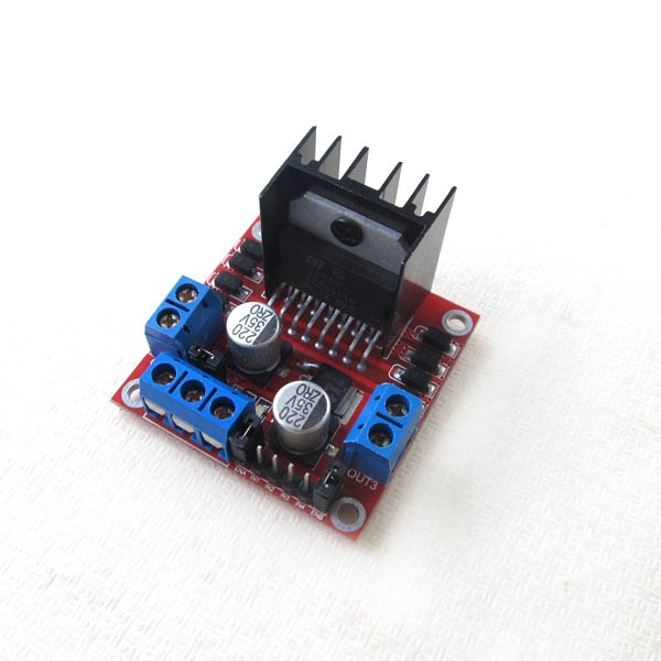
L298N Motor driver module ([m.nu](https://www.m.nu/servo-motorer-robotics/l298-dc-motor-driver-board))
#### Power supply
So, we have a 12 V fan, but the motors on the other hand wants 3-6 V, and the LoPy4 needs an input voltage of 3.5-5.5 V according to the [datasheet](https://alepycom.gitbooks.io/pycom-documentation/content/chapter/datasheets/downloads/lopy4-specsheet.pdf). The solution to this was to use a 12 V-ish battery connected to a 5V voltage regulator circuit. The following components were used for the power supply:
* **11.1V LiPo Battery**: LiPo batteries are lightweight, have high energy density and can provide a lot of power quickly if needed. On the other hand, they are quite expensive and will explode if treated badly (anyone relate?). A common alternative is NiMH-batteries, which are heavier, but more secure and oftentimes cheaper.
* **LiPo tester**: Since LiPo batteries will break if their voltage drops too low, this simple device will howl angrily at a voltage level you can set yourself. Just to be safe.
* **LiPo charger**: Sadly necessary.
* **5V regulator (7805 TO-220) + heatsink**: Converts a higher voltage to a 5V output by radiating the excess as heat. Without proper heat sink, it may not be able to deliver the output current needed for the DC motors.
* **Bypass capacitors**: The 5V regulator wants a 0.33 uF capacitor on the input end, and a 0.1 uF capacitor on the output end. I didn't have a 0.33 uF capacitor, so i used one 0.22 uF and a 0.1 uF capacitor in parallell on the input (which adds up to 0.32 uF). In order to smooth out voltage spikes caused by the motors, a couple more 0.1 uF capacitors were placed closer to the motor driver.
* **Power switch**: I also used female spade terminals and heat-shrink tubing in order to safely connect it with the rest of the build.
### Material summary, links and pricing
In the cases I bought a bundle of things, I've calculated both the total cost and the cost of the actual used material. Most of the linked sellers are Swedish retailers, of which many ship internationally, but everything should be easy to find elsewhere by just googling.
| Thing | Cost of bought material (approx) | Cost of used material (approx)| Link to seller|
| ------------- |:--:|--|--|
| 5 V regulator, 7805 TO-220| $1| $1 |[m.nu](https://www.m.nu/ic-transistorer/5v-15a-linear-voltage-regulator-7805-to-220)
|TO-220 Clip-On Heatsink |$2|$2|[m.nu](https://www.m.nu/blandat/to-220-clip-on-heatsink)
|Ceramic capacitors (0.1 uF and 0.22 uF, as parts of a bundle)|$15|$1|[kopplat.se](https://www.kopplat.se/Produkt/8779/Komponentsats-keramiska-kondensatorer-224-styck)|
|L298N Motor driver|$10|$10|[m.nu](https://www.m.nu/servo-motorer-robotics/l298-dc-motor-driver-board)
|Geared DC Motor x2, 3-6 V|$8|$8|[Electrokit](https://www.electrokit.com/produkt/dc-motor-med-kuggvaxel-148-65rpm-6v-2-pack/)|
|Robot wheels 65mm x2|$3|$3|[Electrokit](https://www.electrokit.com/en/product/robot-wheels-65mm-rubber-tires-2-pack/)|
|M3 nylon standoff:s|$8|$1|[Pchbutik](https://pchbutik.se/osorterat/716-sortiment-med-svarta-m3-nylon-standoffs-180-delar.html?search_query=m3+nylon&results=94)|
|LiPo battery, 11.1V (2-pack)|$56|$28|[Amazon](https://www.amazon.se/gp/product/B089YNFCJP/ref=ppx_yo_dt_b_asin_title_o01_s00?ie=UTF8&psc=1)|
|Screw terminal block connectors|$13|$1|[Amazon](https://www.amazon.se/gp/product/B087RN8FDZ/ref=ppx_yo_dt_b_asin_title_o01_s01?ie=UTF8&psc=1)|
|LiPo battery charger (Requires power supply cable, 11-19V)|$28|$28|[Amazon](https://www.amazon.se/gp/product/B08DXLG9V3/ref=ppx_yo_dt_b_asin_title_o01_s01?ie=UTF8&psc=1)|
|LiPo tester|$6|$6|[kullagergrossisten.se](https://www.kullagergrossisten.se/product/li-po-testare--matare--varnare--1-8s)
|Deans Style T Plug connector |$7|$2|[Amazon](https://www.amazon.se/gp/product/B08CC3P9JR/ref=ppx_yo_dt_b_asin_title_o01_s01?ie=UTF8&psc=1) |
|On/off-switch|$2|$2|[Electrokit](https://www.electrokit.com/produkt/vagomkopplare-1-pol-off-on/)|
|MPU6050 accelerometer and gyro|$7|$7|[Electrokit](https://www.electrokit.com/produkt/mpu-6050-accelerometer-3-axel-monterad-pa-kort/)|
|Caster wheel 16mm|$2|$2|[Electrokit](https://www.electrokit.com/en/product/caster-wheel-16mm/) |
|LoPy4|$46|$46|[Pycom](https://pycom.io/product/lopy4/)|
|LoPy Expansion Board|$21|$21|[Pycom](https://pycom.io/product/expansion-board-3-0/)|
|4-pin PWM fan: Cooler Master|$19|$19|[NetOnNet](https://www.netonnet.se/art/datorkomponenter/kylning/chassiflakt/cooler-master-sickleflow-120-argb-white/1015633.9163/)|
|**Total**|**$254**|**$188**||
## [](#Computer-setup "Computer-setup")Computer setup
In order to program the LoPy4, I used the pymakr extension in VSCode. To get started properly, follow the [instructions](https://docs.pycom.io/gettingstarted/software/) in the Pycom docs on how to set up everything. Make sure the firmware is updated.
## [](#Putting-everything-together "Putting-everything-together")Putting everything together
This isn't a laser cutting tutorial, although if you're curious, the software I'm using while cutting is Lightburn, and the cut out parts are available as SVG files on [GitHub](https://github.com/annpoh/RobotVacuumCleaner).
**Here's how everything is connected**:

### [](#Platform "Platform")Choice of platform
For transmitting and visualizing data, I chose the Pybytes platform. The reason for that is that it felt fairly simple to use, and because it offers ways to interact with external platforms, such as Google Cloud IoT. Pybytes is a cloud platform which provides simple sending of user defined signals, which can be easily displayed and plotted onto your Dashboard.
One drawback of using Pybytes, is that it's difficult to make a remotely *controlled* unit, rather than a *monitored* one. I don't think it's a big problem, but if you want to be able to control your robot remotely, then there are probably better solutions.
Pybytes isn't intended as a very data intensive platform, rather it's more well suited for reporting back sensor some data every now and then. The current implementation of my vacuum cleaner sends the number of collisions since it was turned on, every time it collides. This could become a problem if it gets stuck, and the only symptom is that you stop receiving data. Another solution could be setting a hardware timer with a callback function that reports data every half a minute or so.
### [](#The-code "The-code")The code
The full code of the project is available on [GitHub](https://github.com/annpoh/RobotVacuumCleaner).
#### lib/rvc.py
In this module, I created two classes -- a DC motor class interfacing against the motor driver, and a robot class, interfacing against the motor objects. The robot class also has functionality to control the fan speed, which is not used at the moment (without sending signals, the fan defaults to running at maximum speed, which is good for now). The following excerpt shows the (quite primitive) collision handling process:
```python
def handleCollision(self):
self.stop()
# Collect the randomness<3
turnright = random.choice(True, False) # Generate turn direction
turntime = random.float_between(2.0, 5.0) # Generate turn duration
time.sleep(2)
# Back up before turning
self.moveBackward()
time.sleep(3)
if turnright:
self.turnRight()
else:
self.turnLeft()
time.sleep(turntime)
self.stop()
time.sleep(2)
# Keep going
self.moveForward()
self.collisionCount +=1
```
#### lib/mpu6050.py
The original library is created by Adam Jezek and is available on [GitHub](https://github.com/adamjezek98/MPU6050-ESP8266-MicroPython). I modified it to fit my LoPy-device and project, and added functionality such as calibration of the gyro and accelerometer.
#### lib/keys.py
Config file storing wifi SSID, password and NTP-server.
```python
# Keep this file hidden
SSID = 'NotMyRealNetwork'
PASSWORD = 'NotMyRealPWD'
NTP_SERVER = 'se.pool.ntp.org' # Swedish ntp server
```
#### main.py
The following is an excerpt from the main file of the device
```python
# Sync Real Time Clock
rtc = machine.RTC()
rtc.ntp_sync(keys.NTP_SERVER)
print("Time is synced!")
# Create an instance of the Robot Vacuum Cleaner class
robot = rvc.RobotVacuumCleaner()
# Create I2C instance on bus 0
# Default pins on Lopy4 are P9 (SDA) and P10 (SCL)
i2c = I2C(0, I2C.MASTER, baudrate=115200)
# Create an accelerometer object
accelerometer = mpu.accel(i2c)
accelerometer.calibrate()
print(accelerometer.offsets)
robot.moveForward()
# Indicate that initialization process is done
pycom.rgbled(0x00FF00)
while True:
if checkCollision(accelerometer.get_acceleration()):
robot.handleCollision()
pybytes.send_signal(1, robot.collisionCount)
robot.reportData()
time.sleep(0.01)
```
### Transmitting the data / connectivity
Signals are sent over wifi. The wifi connection is established with the smartconfig tool, which comes with the firmware flashed onto the device. It's a script that runs inbetween the boot.py and main.py files, and is configured on the Pybytes project- and device pages when you're logged in on https://pybytes.pycom.io/.
### Presenting the data
Like I said earlier, for now only the collision count is reported (when the robot registers a collision), which is quite lame. Here are some suggestions of data you could monitor, without changing up the design or components too much:
* The PWM fan has a tachometer pin you can utilize, telling the RPM of the fan. Note that since the LoPy4 has 3.3V logic levels, it could be damaged if the signal gotten is of a higher potential.
* The MPU6050 has both a temperature sensor and gyro which could be of interest.
* If one would implement a more advanced movement pattern, the motor speed (the duty cycle of the enable pins of the motors) could be interesting.
It is of course also possible to add more sensors to the device.
### Finalizing the design
I'm quite happy with how a lot of the things turned out. The shape is practical, minimizing the risk of colliding while turning on the spot. I like that the fan and motors are mounted in a way that makes them easy to take off if needed, and I like that I've at least created something I find it worth keeping on working with.

But there is also a lot of room for improvements. The major one is that the fan doesn't suck hard enough to collect any dust. I haven't bothered to put in a filter at the moment, since it's not capable of sucking up almost anything even without it. One part of the problem is the chassi being a bit too far from the ground, which has to do with the motors; my plan was using a pair of stepper motors that would go inside the chassi, but when I (after actually reading up on them) realised they were going to be way too slow, the new ones was difficult to mount the same way. So in order to move forward with the project, I took an easier way out and put them under the chassi. Other than lowering the design, I will probably also have to make the air intake smaller, and make the volume that the air flows through inside the robot thinner as well.
Another thing about the motors: the solution I have now is quite inefficient energy-wise. The voltage regulator basically burns off the excess voltage and release it as heat. One thing I didn't think of either is the voltage drop caused by the motor driver -- it makes the voltage actually provided to the motors a depressing 3.5V instead of 5. It's enough for a build like this, but motors with a higher voltage rating (which can then be used with a lower duty cycle) is definitely on the wish list. Given the built in, optional voltage regulator onboard the motor driver, the microcontroller could be powered directly from there, minimizing the overall complexity of the system.
 Sign in with Wallet
Connect another wallet
Sign in with Wallet
Connect another wallet