# Ch3 SIMT Core
在本章和下一章中,將研究現代 GPU 的架構和微架構。
GPU 架構的討論分為兩部分:(1)在本章中研究實作運算的 SIMT core,然後(2)在下一章中研究記憶體系統。
**Handling Large Data Sets in Graphics Rendering**
在其傳統的圖形渲染角色中,GPU 存取的資料集如 texture maps,這些資料集太大而無法完全 cache 在晶片上。為了要實現在圖形中所期望的高效能 programmability,既可以隨著圖形模式數量的增加而降低驗證成本,也可以使遊戲開發人員更容易區分他們的產品 [Lindholm et al., 2001]。
**Effective Use of On-Chip Caches**
為此我們有必要採用能夠維持大的 off-chip bandwidth 的架構。因此,今天的 GPU 會同時執行數萬個 thread 。雖然每個 thread 的 on-chip 記憶體儲存量很小,但 cache 仍然可以有效地減少大量的 off-chip 記憶體存取。
- 例如,在圖形工作負載中,可以由 on-chip cache 捕獲相鄰像素操作之間存在的 spatial locality。

圖 3.1 展示了本章討論的 GPU pipeline 的微架構。該圖說明了圖 1.2 中所示的 single SIMT core 的內部組織。
pipeline 可分為 SIMT 前端和 SIMD 後端。
- 由三個 scheduling loop 組成,它們在一個 pipeline 中共同作用:
- 一個 instruction fetch loop
- 包括標記為 Fetch、I-Cache、Decode 和 I-Buffer 的區塊
- 一個 instruction issue loop
- 包括標記為 I-Buffer、Scoreboard、Issue 和 SIMT stack 的區塊。
- 一個 register access scheduling loop.
- 包括標記為 Operand Collector、ALU 和 Memory 的區塊


以下討論由簡入繁,從一個 loop 開始,逐漸描述到最完整的三個 loop,該過程稱為 approximation
# 3.1 單循環近似 (One-Loop Approximation)
首先考慮具有 single scheduler 的 GPU。
如前所述,為了提高效率,thread 被組織成 NVIDIA 稱為 "warp" 和 AMD 稱為 "wavefronts" 的團體單位。因此,scheduling 的單位是一個 warp。
- **Scheduling and Execution Process**:
1. 在每個週期中,hardware 選擇一個 warp 進行 scheduling
2. 用 warp’s program counter 來 access an instruction memory ,並抓取目標指令
3. 抓到指令之後,decode 指令,並把 source operand registers 從 register file 中抓過來
4. 同時,確定 SIMT execution mask 值.
5. 完成後,以 SIMD 方式往下繼續執行
6. 給定特定 Thread 的 SIMT execution mask(should be '1', active),Each thread in the warp 在特定的 function unit 執行指令
以下小節描述如何確定 SIMT execution mask 並將它們與現代 GPU 中也使用的 predication 進行比較。
在確定 execution mask 和 source register 可用後,以 SIMD 方式進序執行。
如果設定了 SIMT execution mask,則每個 thread 都在與通路 (lane) 關聯的 function unit 中執行運算。
**Heterogeneous function unit**
- What?
- 是現代 CPU, GPU 常見的設計
- 只能執行特定的指令、功能
- 相對於 **homogeneous units**,可以執行所有指令
- 種類:
- **SFU 特殊功能單元**: Optimized for complex mathematical operations like trigonometry.
- **Load/Store Unit**: Handles memory operations, such as loading data from or storing data to memory.
- **Floating-Point Unit**: Optimized for floating-point arithmetic operations.
- **Integer Function Unit**: Focused on integer arithmetic.
- **Tensor Core (從 Volta 開始)**: Designed for deep learning computations, especially matrix operations fundamental in neural networks.
所有 function unit 名義上包含的 Channel 與 warp 中的 thread 數量一樣多。
然而,一些 GPU 使用了不同的實作,其中單個 warp 或 wavefront 可以在多個時鐘週期內執行
- 這是透過以更高的頻率為 function unit 提供時脈來實現的,這可以以 **增加能耗** 為代價來實現 **更高的單位面積性能**。
- 為 function unit 實現更高時脈頻率的一種方法是將它們的執行 pipeline 化(each stage being processed in a different clock cycle)或增加它們的 pipeline depth (number of stages)。
## 3.1.1 SIMT EXECUTION MASKING
### SIMT Execution Model
從功能的角度來看,它為程式設計師提供了單一 thread 完全單獨執行的抽象。這種程式模型可能僅透過 predication 就能實現。然而,在目前的 GPU 中,它是透過將傳統的 Predication(引述碼) 與我們稱為 SIMT stack 的 **stack of predicate masks** 相結合來實現的。
### Predication 引述碼 (補充)
不是 "prediction" Predication 和預測沒有關聯。
- predication是一種實現 control flow transfer(如分支)的方法。它透過在指令中加入一個邏輯值(這個值叫做predicate),控制指令是否可以修改當前系統狀態。
- 簡單來說,這是另一種用來控制 conditional branches 的機制,是一種「**active mask**」
- 如果 Predication 為真,可以寫入
- 反之則不行
What?
- Condition codes (predication) are used in older architectures to emulate true branching. If-then statements compiled to these architectures must evaluate both taken and not taken branch instructions on all fragments.
- The branch condition is evaluated and a condition code is set. The instructions in each part of the branch must check the value of the condition code before writing their results to registers.
- As a result, only instructions in taken branches write their output.
- Thus, in these architectures all branches cost as much as both parts of the branch, plus the cost of evaluating the branch condition. Branching should be used sparingly on such architectures.
每一個 warp,在執行的時候,都是同一個指令,GPU 中沒有像 CPU 那樣的分支預測、rollback 等各種機制,所以 **當 GPU 中出現分支的時候,如下圖,GPU 使用 Predicate Register 來解決**。

右邊是 I-buffer,可以看到每一行有三個標記:
1. Entry:這裡為 V,代表 vacant,也就是這個指令準備好被取走運行了。
2. Inst+Warp:對應的實際的指令,以及是具體的哪一個 warp。
3. Scoreboard,為了解決亂序執行時資料的 RAW/WAW/WAR 問題。

這裡主要講 2,可以看到在以上程式碼中,第一個和第二個 Thread 執行 C 指令,第三個和第四個執行 D 指令,但是取指令運行是各個 thread 一起的,這時候就輪到 Predicate Register 了,它的作用能當成一個蒙版,覆蓋上去,覆蓋住的標記為 Active,沒覆蓋到的為 inactive,來區分這條指令運行時不同 thread 的分歧。
這樣的缺點也有,那就是在分支很多的時候,會降低整個 SM 的使用效率。
## SIMT stack
在傳統方法中,支援預測的 CPU 透過使用多個 predicate registers 來處理巢狀控制流,並在文獻中提出了支援 across lane predicate tests
而 SIMT stack 有助於有效處理所有 thread 在獨立執行時出現的兩個關鍵問題。
1. **Nested Control Flow**: Situations where one branch in the code is dependent on another.
2. **Skipping Computation**: Avoiding execution of certain code paths by all threads in a warp, which can lead to significant computational savings in complex control flow.
專利和指令集手冊中描述了幾種實作,在這些描述中,SIMT stack 部分由專用於此目的的特殊指令來管理。
- 在此,我們引入稍微簡化的版本,假設硬體負責管理 SIMT stack,且假設 GPU 的每個 warp 有四個 threads。
為了描述 SIMT stack,我們使用圖 3.2 展示了包含兩個嵌套在 do-while 循環中的分支的 CUDA C 程式碼,圖 3.3 展示了對應的 PTX。圖 3.4,再現了 Fung 等人 [Fung et al., 2007] 論文中的圖 5,說明了此程式碼如何與 SIMT stack 交互。


實心: 代表 thread 在執行對應 code block
空心: 代表 thread is masked off
- 在例子中,第四個 thread 為了符合 SIMD 的條件,要錯開 B Block,等到後面 (after several cycles) F Block 才能執行另一個 code path (different instructions)
執行順序:
- 上述 SIMT stack 中在初始化 c 圖部分,TOS 指向下一個 Next PC 為 B,即下一個要執行的指令為 B 出現分支,執行 B 指令的 mask 為 1110。
- 而 B 指令的 entry 指向 d 圖的 TOS,即指向完 B 之後開始執行 C 執行
- 而 B 執行聚合點指令為 E,即執行完 C 之後還要執行聚合點同樣為 E 的指令即 D 指令,**只有聚合點都是 E 的指令執行完畢之後,才能繼續往下執行**,
- 而執行的指令則為 E 指令。此時同樣 E 指令的聚合點指令為 G,需要把所有聚合點位 G 的指令執行完畢之後才能執行 G 指令。
Figure 3.4 中的 SIMT stack 狀態大致按以下步驟變化:
Initial State:
- 程式開始執行時,只有 1 個 entry,它的 Next PC 為 Block A。
- 在 Figure 3.3 中的第一個基本區塊是 Block A,而執行完 Block A 後,有兩個可能的執行路徑:
- 路徑 1:由第 6 行程式碼跳到 Block F 執行;
- 路徑 2:執行第 7 行程式碼的 Block B。
- 由於 Block F 和 B 的 IPDOM 為 Block G,故 entry 1 的 Next PC 由 Block A 轉變成 Block G。
- 故 entry 2 和 entry 3 的 Next PC 分別為 Block F 和 B。由於 Block F 和 B 的 IPDOM 為 Block G,故 Ret. PC 為均為 Block G。
After Divergent Branch
- 在 Figure 3.3 中執行完 Block B 後,有兩種可能的執行路徑:
- 路徑 1:由第 9 行程式碼跳到 Block D;
- 路徑 2:執行第 10 行程式碼的 Block C;
- 由於 BlockD 和 C 的 IPDOM 為 Block E,故 entry 3 的 Next PC 由 Block B 轉變成 Block E。
- 故 entry 4 和 entry 5 的 Next PC 分別為 Block D 和 C。由於 BlockD 和 C 的 IPDOM 為 Block E,故 Ret. PC 為均為 Block E。
After Reconvergence
- 在 Figure 3.3 中執行完 Block C 後,Next PC 變成 Block E,與 Ret. PC 一致,故該 entry 出 stack;
- 在 Figure 3.3 中執行完 Block D 後,Next PC 變成 Block E,與 Ret. PC 一致,故該 entry 出 stack;
- 在 Figure 3.3 中執行完 Block E 後,Next PC 變成 Block G,與 Ret. PC 一致,故該 entry 出 stack;
- 在 Figure 3.3 中執行完 Block F 後,Next PC 變成 Block G,與 Ret. PC 一致,故該 entry 出 stack;
- 在 Figure 3.3 中執行完 Block G 後,Next PC 變成 Block A。此時恢復成 1.Initial State 最開始的狀態。
### Warp divergence(補充)
> In SIMT, threads execute in lockstep within a warp. If a thread's execution mask is set (meaning it is active), it proceeds with the operation; otherwise, it is idle.
> This means that even if only one thread in a warp needs to execute a particular instruction, the entire warp must wait until this instruction is completed.
> This can lead to inefficiencies known as "**warp divergence**"
Pascal 和早期的 NVIDIA GPUs 以 SIMT(單指令、多 thread )方式執行一組共 32 個 thread (稱為 warp)。 Pascal 中,每個 warp 使用單一在所有 32 個 thread 中共享的 PC,並結合一個 **active mask** 來指定 warp 中的哪些 thread 在任何給定時間是活躍的。
- 這意味著不同的執行路徑(divergent execution path)會讓一些 thread 處於 non-active,因為不同路徑代表執行不同指令,而為了符合 SIMD datapath 條件 (在單一 warp 中的每個 thread 在 each cycle 只能執行一個 instruction), GPU 在一個 warp 中,直接 serialize execution of threads (of different paths) 來讓 thread 在程式中執行不同 execution path
- 原始 mask 被存儲,直到 warp 再次收斂(通常在發散部分的末尾),此時 mask 被還原,thread 再次運行在一起。
- 為了減少 reconvergence stack 的深度,先執行 active thread 最多的分支,然後再執行 active thread 少的分支。
**How?**
1. **在 divergent points 處理**: 在 GPU 程序中的分歧點(如 `if-else` 語句)時,GPU 會根據條件給 thread 分配 '1'(活動)或 '0'(非活動)。
2. **序列化(serialize)處理每組 threads**:
- GPU 接著會 serialize 處理每組 threads 來處理這些 divergent paths。
- 更新 execution mask 以確保在任何給定時間只有相關的 threads 處於活動狀態。
- 當發生分歧時,GPU 更新 execution mask 以只啟動那些正在執行當前路徑的 threads。它執行此路徑的所有指令。
- 一旦一條路徑的指令完成,GPU 更新 execution mask 以切換至分歧到不同路徑的下一組 threads。
3. **處理完所有路徑後,warp 重新匯聚**: 恢復平行執行。
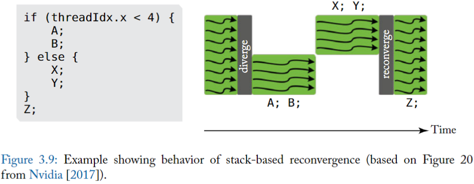
**如何使用這種 serialization?**
- 使用 stack,包含
- **reconvergence program counter (RPC),**
- A reconvergence point is a location in the program where threads that diverge can be forced to continue executing in lock-step.
- **the address of the next instruction to execute (Next PC),**
- **an active mask.**
- 代表該 warp 中,要執行指令的 threads
- 記錄目前指令哪些 thread 執行,哪些 thread 被屏蔽(masked)
- 怎麼決定放到 stack 上的順序?
- 「It is best to put the entry with the most active threads on the stack first and then the entry with fewer active threads」
- **為了減少 reconvergence stack 的深度,先把執行活躍 thread 最多的分支放到 stack 上,然後再放執行活躍少的分支。**
- ( d ) 是按照此順序
- ( c ) 是剛好相反
## 3.1.2 SIMT deadlock 與 stackless SIMT 架構
在 NVIDIA 的 Volta GPU 架構的詳細資訊中 [NVIDIA Corp., 2017]。他們強調的更新是: behavior of masking under divergence and how this interacts with synchronization.
其實,SIMT stack-based 的實作可能會導致 deadlock 情況,ElTantawy 和 Aamodt [2016] 稱之為「SIMT deadlock」。學術工作已經描述了用於 SIMT 執行的替代硬體 [ElTantaway 等人,2014 年],只需稍作改動 [ElTantawy 和 Aamodt,2016 年],就可以避免 SIMT 死鎖。
NVIDIA 將他們的新 thread divergence management 稱為 **Independent Thread Scheduling**,該機制的描述表明它們實現了類似於上述學術研究中所建議的行為。下面,我們首先描述 SIMT deadlock問題,然後描述一種避免 SIMT deadlock 的機制,該機制與 NVIDIA 對 Independent Thread Scheduling 的描述一致,並且在最近的 NVIDIA 專利申請中公開 [Diamos et al., 2015] 。
### SIMT DEADLOCK
>Behavior of masking under divergence, interacting with synchronization, can lead to a deadlock condition called “SIMT deadlock”
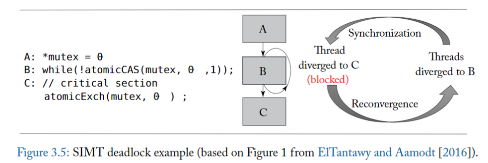
圖 3.5 的左側說明了 SIMT deadlock 問題,中間部分顯示了對應的控制流程圖。
- A 將共享變數 mutex 初始化為零,代表鎖是 idle 的。
- 在 B 行,warp 中的每個 thread 都執行 atomicCAS 操作,該操作對包含 mutex 的記憶體位置進行比較和交換 (compare-and-swap) 操作。
- atomicCAS 運算是一個編譯器內嵌 (intrinsic) 函數,它被轉換成 atom.global.cas PTX 指令。
- 邏輯上,compare-and-swap 首先讀取 mutex 的內容,然後將其與第二個輸入 0 進行比較。如果 mutex 的目前值為 0,則 compare-and-swap 操作將 mutex 的值更新為第三個輸入 1,而 atomicCAS 傳回的值是 mutex 的原始值。
- 重要的是,compare-and-swap 以原子方式為每個 thread 執行上述邏輯操作序列。
- 因此,atomicCAS 對任何單一位置的多次訪問,由同一個 warp 中的不同 thread 進行,都是 serialize ,代表有取用 mutex 的先後順序存在。
- 🚨 由於圖 3.5 中的所有 thread 都存取同一個記憶體位置,因此只有一個 thread 會看到 mutex 的值為 0,其餘 thread 會看到值為 1。
- 接下來,重點關注 atomicCAS 返回後, B 行的 while 迴圈會發生什麼事。**在這邊,不同的 thread 看到不同的迴圈條件**。
- 具體來說,因為返回值不同,導致一個 thread 想要退出循環,而其餘 thread 想要留在循環中。
- 退出循環的 thread 將到達重新 reconvergence point,因此將不再在 SIMT stack 上處於活躍狀態,因此無法執行 atomicExch 操作以釋放 C 行上的 mutex。
- 留在循環中的 thread 將在 SIMT stack top 處於活躍狀態並將無限循環。
- 由此產生的 thread 之間的 thread dependency 引入了一種新形式的死鎖,ElTantawy 和 Aamodt [2016] 稱為 SIMT 死鎖,**如果 thread 在 MIMD 架構上執行,這種死鎖將不存在**
::: info
**前面的內容稍微總結一下:**
:::
SIMT mask 可以解決 warp divergence 問題,透過 serialize 讓分支執行完畢之後,thread 在 reconverge point 時可以重新聚合在一起。
- 但對於一個程式來說,如果出現分支就意味著這每個分支的指令和處理不一致,這就容易造成共享資料的一致性問題
- 失去一致性就意味著在同一個 warp 內的 thread 如果存在分支,則 thread 之間不能夠交互或交互數據,
- 在一些實際演算法中為了進行數據交互則需要使用 lock 機制,而 mask 恰恰會因為排程問題造成一個死鎖 deadlock 問題.
- The atomicCAS instruction ensures that exaclty one thread gets 0 assigned to prev, while all others get 1. When that one thread finishes its critical section, it sets the semaphore back to 0 so that other threads have a chance to enter the critical section.
理想的執行步驟:
- Step1:在 Block A 時,在 warp 中所有 thread 執行 Block A,從而將共享變數 `*mutex` 初始為 0,代表鎖定是空閒的。
- Step2:在 Block B 時,atomicCAS()是原子操作,只允許一個 thread 進行,故 warp 中的 1 個 thread 進行 atomicCAS()操作,鎖定 `*mutex` 共享變量,另外 31 個 thread 進行 while()循環等待。
- Step3:在 Block C 時,釋放 `*mutex` 共享變數
造成上述死鎖 deadlock 問題原因恰恰是 SIMT mask 所造成的。問題出在 step2,因為 SIMT stack 的 scheduling 原則,是先執行活躍數 thread 最多的分支,上述例子是先執行分支為 31 個 thread 的情況,而這 31 個 thread 會一直卡在 while()循環,而剩下的拿著鎖的 1 個 thread 此時處於 inactive 狀態,因為上述 31 個 thread 一直處於循環之中而造成得不到 schedule。這種情況就造成了死鎖,而無法繼續向前執行。
**出現這種問題的本質是 thread block 中的所有 thread 共享 1 個 PC 指針,這導致無法進行細粒度的 thread 操作。**
### 解法: Independent Thread Scheduling
deadlock 問題長期依賴困擾 GPU 應用開發人員。 NV 一直到 V100 GPU 中才得到解決,《NVIDIA TESLA V100 GPU ARCHITECTURE》中,NV 將解決 deadlock 問題作為一個亮點,V100 白皮書中指出了對上述問題對 SIMT stack 模組進行了改進:
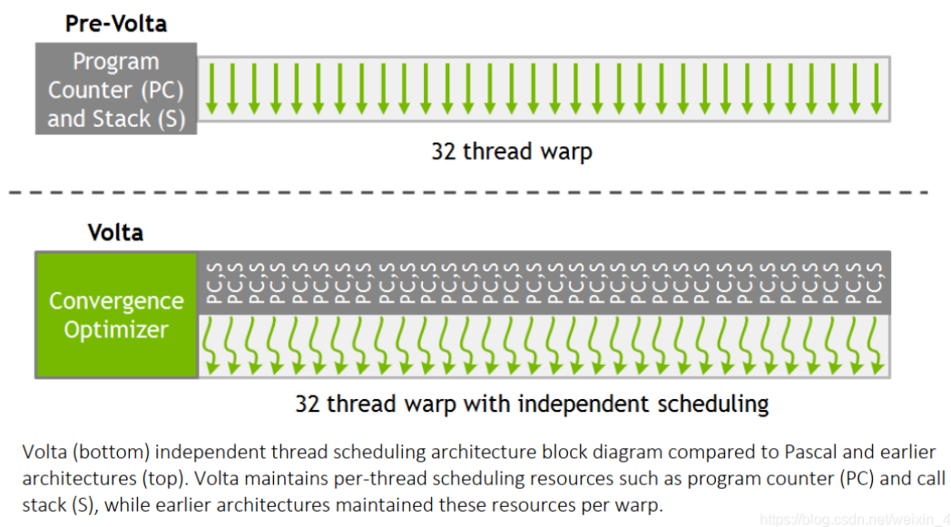
為了解決這個問題,**V100 中 NV 為 warp 內每個 thread 都分配了一個 PC 指針和 Stack**,這樣將 PC 指針的顆粒度細化到了每一個 thread 中,讓每一個 thread 可以在 warp 中進行 diverge 和 converge。
但是這樣就於 GPU 的根基 SIMT 執行模型又有明顯的衝突,因為這樣每個 thread 都有自己的 PC,豈不是跟 CPU 沒什麼本質上的差異。
- 為了不損失平行性以及保持 SIMT 的執行模型,在硬體排程時仍然還是使用 warp 為單位。
- 在 V100 內部調用中,硬體還是使用 warp 這一單位進行 thread scheduling,V100 內部中使用了 **schedule optimizer** 硬體模組決定哪些 thread 可以在一個 warp 內進行 schedule (這樣就涉及到另外一種技術 **rearrange thread** ),講相同的指令重新進行組織排佈到一個 warp 內,執行 SIMD 模型,以確保最大利用效率。
- **scheduler optimizer**: determines how to group active threads from the same warp together into SIMT units
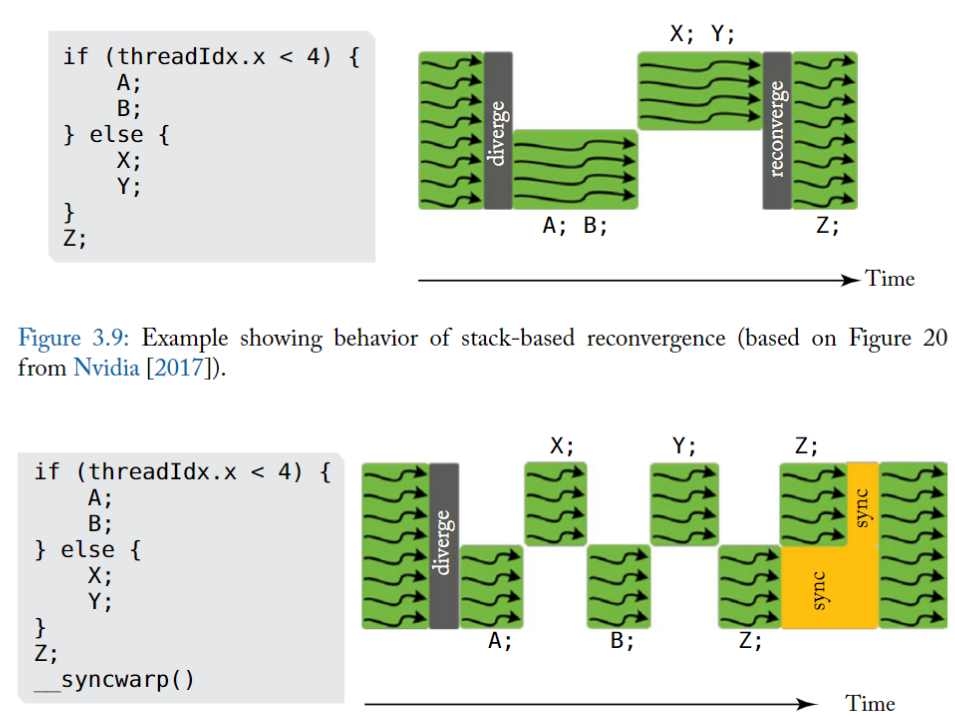
上述例子為 V100 中官方例子,其中有兩個分支 A 和 B ,X 和 Y,warp 依照串列執行兩個分支。
上圖中有一個明顯改進就是 執行 A 之外 可以切換到執行 X,這樣做的好處**可以隱藏 A 記憶體操作延遲,這樣交替執行更能提高硬體利用率**。同時也可以發現兩個分支的聚合點 Z,並沒有等待所有分支執行完畢之後再一起聚合執行,這是因為無法辨識到 Z 是否依賴各自的結果,所以只能各自執行以便提高效率。
如果有些演算法需要聚合之後再同步執行 Z,NV 提供了另一個函數\_\_syncwarp(),可以是 Z 之後的程式碼進行聚合執行,如上圖下方。
所以,回到前面的問題,現在在 Volta 的架構下,同一個 warp 中的 thread 可以獨立地被排程,而不會因為 thread 執行數量而被侷限在同一個 stack entry 裡面,就不會造成 deadlock
## Stackless branch reconvergence mechanism
> replace the stack with per warp convergence barriers
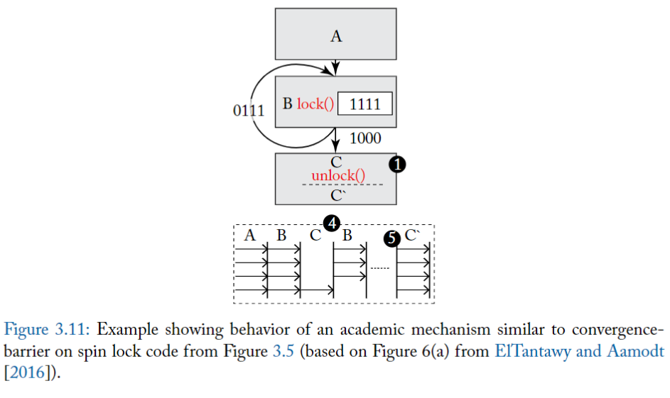
使用 Convergence barrier 來實作出 independent thread scgeduling
### Convergence barrier
Stackless branch reconvergence mechanism,類似於 NVIDIA 最近的美國專利申請 [Diamos et al., 2015]。此機制與 NVIDIA 迄今對 Volta 重新收斂處理機制的描述一致 [Nvidia, 2017]。**關鍵思想是用每個 warp 的 convergence barriers 取代 stack**
下圖顯示了 NVIDIA 專利申請中所述的每個 warp 維護的各個欄位 (field),圖 3.8 提供了一個相應的範例來說明 convergence barriers 的操作。
實際上,該提案提供了 Multi-Path IPDOM [ElTantaway et al., 2014] 的替代實現,將在第 3.4.2 節以及早期的學術著作中進行描述。convergence barriers 機制與 Fung 和 Aamodt [2011] 中所描述的 warp barrier 的概念有一些相似之處。
為了幫助解釋下面的 convergence barriers 機制,我們在圖 3.8 中的程式碼上執行單一 warp,它顯示瞭如圖 3.7 所示的 CUDA 程式碼產生的控制流程圖。


圖 3.6 中的 field 是儲存在 register,被 HW warp scheduler 所使用
- 圖 3.6 中的 register 可能使用通用 register 或專用 register 或兩者的某種組合來實現(專利申請中沒有說明)
- Barrier Participation Mask:
- 用來追蹤維護哪些 thread 歸屬於哪個 convergence barrier
- 因為在一個 kernel 中可能會存在多個分支,意味著會出現多個 convergence barrier,每個 warp 可能會參與到多個 convergence barrier,被同一個 Barrier Participation Mask 紀錄的 threads 通常會互相等待,直到都達到了 common point(類似 reconvergence point ).
- 可以搭配下方的 Barrier State
- Barrier State: 用於追蹤哪些 thread 已經達到了 convergence barrier 狀態。
- Thread State: 用來記錄 warp 中 threads 的狀態,
- able to execute
- blocked at convergence barrier
- has yielded
- yielded 狀態可能用於使 warp 中的其他 thread 在可能導致 SIMT deadlock 的情況下繼續向前推進,以通過 convergence barrier
- Thread rPC: non-active thread 要執行的下一個指令地址
- Thread Active: 1-bit,記錄 thread 是否處於啟動狀態
- 上述各 entry 大小和 warp 相關,如果 warp 為 32 個,則各自都有 32 個資訊。
**不同欄位的補充說明:**
- 假設一個 warp 包含 32 個 thread,barrier participation mask 位元寬是 32 bit。
- bit = 1 代表 warp 中的對應 thread 參與了這個 convergence barrier。
- warp scheduler 使用 barrier participation mask 在特定的 convergence barrier 位置停止 thread,該位置可以是分支的 immediate postdominator 或其他位置。
- 在任何給定時間,每個 warp 可能需要多個 barrier participation mask 來支援 nested-control flow
- barrier participation mask 有 32 bit 寬,如果讓每個 thread 都用 register 來儲存一份 barrier participation mask 會顯得很多餘。然而,由於 control-flow 可以 nest 到任意深度,給定的 warp 可能需要任意數量的 barrier participation mask,使得 mask 便於管理
執行過程(補充):

- 為了初始化 convergence barrier participation mask,採用了特殊的「**ADD**」指令。
- 當 warp 執行此 ADD 指令時,所有處於 active 的 thread 都在 ADD 指令指示的 convergence barrier 中設定了它們的對應的 bit。
- 在執行分支後,一些 thread 可能會 diverge,這意味著要執行的下一條指令的位址(即 PC)將會不同。
- 當發生這種情況時,scheduler 將選擇具有共同 PC 的 thread subset,並更新 Thread Active 欄位以啟用 warp 中這些 thread 的執行。這樣的 subset 被稱為「**warp split**」
「**WAIT**」指令用於在達到 convergence barrier 時停止 warp split。
- WAIT 指令包括一個 operand 來指示 convergence barrier 的 ID。 WAIT 指令的作用是將 warp split 中的 thread 加入到特定 barrier 的 Barrier State register 中,並將 thread 的狀態改為 block。
- 一旦 barrier participation mask 中的所有 thread 都執行了對應的 WAIT 指令,thread scheduler 就可以將所有 thread 從原始 warp split 切換為 active,且維持了 SIMD 效率。
**convergence barrier 的優點:**
- 與 stack-based 的 SIMT 相比,透過 convergence barrier,scheduler 可以在不同 groups of diverge threads 間自由切換。允許了「當一些 thread 獲得了 lock 而其他 thread 沒有時, warp 中的 thread 還可以向前推進」

### 3.1.3 WARP SCHEDULING
Each core in a GPU contains many warps
warp scheduling 為 GPU 執行過程中非常關鍵的一部分,直接決定了每個 clock 哪些執行緒在 warp 得到排程。
為了簡化討論,有個前提是在每個 warp 執行時,每個 warp 都只能同時執行相同指令,只有前一個指令執行完畢之後,warp 才會透過排程執行下一個指令。
在一種理想 GPU 狀態下,如果假設 GPU 內的每個 warp 內的 thread 的 memory latency 都相等,那麼可以透過在 warp 不斷切換 thread 可以隱藏記憶體存取的延遲
- 例如在同一個 warp 內,此時執行的記憶體讀取指令,那麼可以採用非同步方式,在讀取記憶體等待過程中,下一刻切換 thread 其他指令進行平行執行,這樣 GPU 就可以一邊進行讀取記憶體指令,一邊執行計算指令動作。
此方法主要時因為 **GPU 將不同類型的指令分配給不同的單元執行**,讀取記憶體使用 LD/ST 硬體單元,而執行計算指令可能使用 INT32 或 FP32 硬體單元。這樣就可以透過循環呼叫(round robin)隱藏記憶體延遲問題。在理想狀態下,可以透過這種 round robin 方式完全隱藏掉記憶體延遲問題。而理論上,如果 每個 core 可以負擔的 warps 數量增加,就可以增加 throughput/core。
然而這邊存在一些 trade-off。使用 RR 的排程方式時,就需要在每個時鐘週期內不斷切換 thread ,而每個 thread 都需要有自己的專用 register 保存私有相關信息,隨著 warp 切換數量不斷增加,warp 所需要的 register 會不斷增多,同樣會造成晶片分配給 register 的面積不斷增大。
- 同樣在固定面積大小的晶片上,隨著 warp 數量增加,core 的數量將不斷減少,
- core 數量減少將造成性能下降,反回來會不足以完成隱藏內存延遲。
在實際情況中,記憶體延遲問題還取決於 應用程式存取的記憶體位置(locality)以及每個執行緒對 off-chip 記憶體的競爭情況。
最後,scheduling policy 和 GPU memory system 的關係,是過去大量研究的主題
# 3.2 TWO-LOOP APPROXIMATION
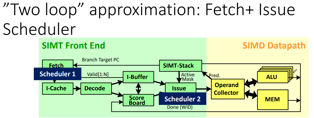
目的: 在能夠 hide latency 的前提下,減少每個 core 所需的 warp 數量
- it is helpful to be able to issue a subsequent instruction from a warp while earlier instructions have not yet completed. => **Able to detect data dependency**
- To provide such dependency information it is necessary to first fetch the instruction from memory so as to determine what data and/or structural hazards exists
方式: 善用 Instruction-Level Parallelism, ILP,將指令執行的時間重疊起來,使程式執行得更快。
硬體
- 多加一個 Instruction buffer
- 完成 cache access 之後, instruction 儲存的地方
- first-level instruction cache backed by one or more levels of secondary (typically unified) caches
- can also help in hiding instruction cache miss latencies in combination with instruction miss-status holding registers (MSHRs)
- 多加一個 scheduler,在 Instruction buffer 中挑出其中一個來放到 pipeline
成果:
在雙循環架構中,第一個循環選擇在 instruction buffer 中還有空間的 warp,尋找其 PC 並執行 instruction cache access 以獲得下一條指令。第二個循環在 instruction buffer 中選擇一條沒有特殊依賴關係的指令,並將其送到執行單元。
補充:
- **Instruction memory**
- 是以 L1 Instruction cache 所實作,是由一個或多個 L2/L3 unified cache 所支持 ( A unified cache 可以儲存 data 和 instructions)
- Secondary caches often include levels L2 and L3. They can be either dedicated to storing instructions only (instruction cache) or data only (data cache), or they can be unified.
- **Instruction buffer**
- why?
- 可以結合 instruction miss-status holding registers 來幫助隱藏 instruction cache miss latencies
- how?
- 在 cache hit / fill from cache miss 之後,指令的訊息就會放在 instruction buffer
- 設計方式,可以直接幫每個 warp 儲存一到兩個指令
#### 如何偵測同一 warp 中指令之間的 data dependency ?
有兩個在傳統 CPU 架構中偵測指令之間依賴關係的方法:
- 記分板 (scoreboard)
- 記分板可以設計為支援順序執行(in-order)或亂序(out-of-order)執行。
- 支援亂序執行的記分板(如 CDC 6600 中使用的記分板)相當複雜。
- 另一方面,單執行緒,順序 CPU 的記分板非常簡單:
- 記分板中的每個 register 都以 1 bit 表示,只要送出將寫入該 register 的指令,就會 set 該 bit。
- 而任何想要讀取或寫入在記分板上已經 set 對應 bit 的 register 的指令都會停止 (stall),直到該 bit 被寫入 register 的指令清除。
- 這可以防止先寫後讀 (RAW) 和先寫後寫 (WAW) hazzard。
- 當與順序指令問題結合使用時,若前提是 register file 的讀取被限制為 in-order 發生(通常順序 CPU 是這樣設計)這個記分板可以防止先讀後寫 (WAR) hazzard。
- 鑑於它是最簡單的設計,因此將消耗最少的面積和能量,所以 ==GPU 實現了順序記分板==。
- 保留站 (reservation station)。
- 用於消除 name dependency 並引入 Associative Logic 的使用需求。
然而,in-order scoreboard 在支援多個 warp 時存在挑戰。
第一個問題:
上述簡單 in-order scoreboard 設計的第一個問題是現代 GPU 中包含大量 register 。每個 warp 最多 128 個 register ,每個 core 最多 64 個 warp,每個 core 總共需要 8192 bit 來實作記分板。
第二個問題:
- 上面描述的 in-order scoreboard 設計的另一個問題是遇到 dependency 的指令必須在記分板中重複查找 operand,直到它所依賴的前一條指令將其結果寫入 register file。
- 對於單 thread 設計,這沒怎麼引入複雜性。然而,在 in-order 送出指令的多執行緒處理器中,來自多個執行緒的指令可能正在等待更早的指令完成。
- 如果所有此類指令都必須探測 (probe) 記分板,則需要額外的讀取連接埠。
- 現代 GPU 支援每個 core 最多 64 個 warp,並且最多支援 4 個操作數,允許所有 warp 在每個週期探測記分板,這將需要 256 個讀取端口,這是非常昂貴的設計。
- 一種替代方法是限制每個週期可以 probe 記分板的 warp 數量,但這限制了可以考慮被排程的 warp 數量。此外,如果檢查的指令都沒有依賴關係,即使其他無法檢查的指令碰巧沒有依賴關係,也不會送出指令。
**這兩個問題都可以使用 Coon [2008] 等人提出的設計來解決**。該設計不是在每個 warp 的每個 register 中保留 1 bit,而是在每個 warp 中包含少量(在最近的一項研究 [Lashgar 等人,2016 年] 中估計約為 3 或 4 個)entry,其中每個 entry 代表的是「已經送出(issue)但尚未完成執行的指令寫入的 register」。常規的 in-order scoreboard 在 送出指令和寫回指令時都會被存取。相反,Coon 等人的記分板是在將指令放入 instuction buffer 以及將其結果寫入 register file 時存取的。
當從 instruction cache 中取出一條指令,並將其放入 instruction buffer 時,對應 warp 的記分板 entry 將與該指令的 source register 和 destination register 進行比較。
這會產生一個短的位元向量 (bit vector),一個 bit 對應 warp 的記分板上的每個 entry(3 或 4 bit)
- 如果 bit = 1,代表記分板中的對應 entry 與指令的任一 operand 匹配。
- 然後將該 bit vectir 與指令緩衝區中的指令一起複製。
- 在所有 bit 都被清除之前,instruction scheduler 不能考慮送出這條指令,這可以透過將向量的每個 bit 送入 NOR 來確定。
- instrction buffer 中的 dependency bit 在指令將其結果寫入 register file 時清除。
- 如果一個給定的 warp 的所有 entry 都用完了,那麼可能停止所有 warp fetching,可能該指令被丟棄並且必須再次 fetching。
- 當一條已執行的指令準備好寫入 register file 時,它會清除記分板中分配給它的 entry,並清除儲存在 instruction buffer 中的來自同一 warp 的任何指令的 dependency bit。
# 3.3 THREE-LOOP APPROXIMATION
如前所述,為了隱藏較長的記憶體延遲,有必要支援每個 core 上有多個 warp;
為了支援多個 warps 之間的 cycle by cycle 的切換,必須有一個大的 register file,其中包含每個正在執行的 warp 的獨立的 physical register。
例如,在 NVIDIA 最近的 GPU 架構(例如,Kepler、Maxwell 和 Pascal 架構)上,此類 register 包含 256 KB。
SRAM 記憶體的面積與連接埠數成正比。
- 而 register file 的簡單實作要求 每個 cycle 送出的每條指令中的每個 operand 都要有一個 port
減少 register file 面積的一種方法是,使用 **多個 single port 的記憶體 bank** 來模擬大量連接埠。
雖然可以透過將這些 bank 暴露於指令集架構來實現這種效果,但在某些 GPU 設計中,出現了一種稱為操作數收集器(**operand collector**) 的結構 [Coon et al., 2009, Lindholm et al., 2008b, Lui et al.。 , 2008] 用於以更透明的方式實現這一目標。
**operand collector 有效地形成第三個 scheduling loop。**
::: info
TL; DR
:::
1. **Traditional Approach - Staging Registers**:
- 傳統的 microprocessor 設計中,會在 指令執行的過程中使用 staging registers
- 當指令抵達 register read stage (where it needs to read its source operands from the register file), 會把拿出來的 operands 暫時存放在 staging registers 中. 方便指令在接下來的 pipeline stage (execute) 中能夠方便存取,而不用重新回到 register file 中存取,提高 pipeline 的效率。
- 潛在問題: **bank conflict**
- Bank conflicts occur when multiple threads attempt to access data from the same memory bank simultaneously, leading to delays.
2. **Key Change - Introduction of Collector Units**:
- 我們用 collector units 來替代 staging register
- Functionality of Collector Units:
- Collector units 跟 staging registers 做差不多的事,但更有效率
- 當進入到 register read stage,每個 instruction 都會被分配到一個 collector unit
- collector unit 會幫 對應的 instruction 存放 source operands
- 好處:
- 更有效率,因為同時有多個可用的 collector units,允許多個 instructions 可以同時進入 register read stage(多個 instructions 可以同時讀取各自的 source operands)
- 更好地處理 bank conflict
- A bank conflict 發生在,different instructions 同時都想要存取相同部分的 register file,導致 delay
- 其中一個 instruction 如果因為 bank conflict 而遇到 delay,其他 instruction 仍然可以繼續從其他部分的 register file 來讀取 operands
- 這種 讀取的 overlap 減少了 bank conflict 對於 throughput 的影響
### 沒有使用 operand collector 的情況:
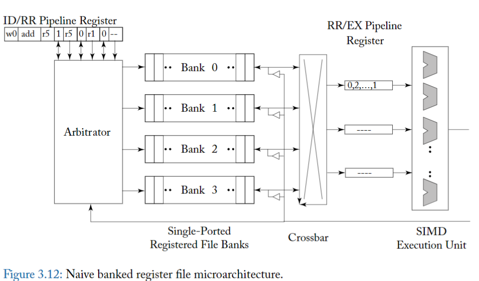
為了更好地理解 operand collector 解決的問題,首先考慮圖 3.12,它顯示了一個簡單的微架構,用於提供增加的 register file bandwidth。
此圖顯示了 GPU instrution pipeline 的 register 讀取階段(read),其中 register file 由四個單埠邏輯 register bank 組成。
- 在實務上,由於 register file 非常大,每個邏輯 bank 可以進一步分解為更多的實體 bank(未示出)。
- logical bank 透過 crossbar 連接到 staging register (標記為「pipeline register 」),這些 staging register 在將 source operand 傳遞給 SIMD 執行單元之前會先緩衝 source operand。
- arbiter (Arbiter) 控制對各個 bank 的 access,並透過 crossbar 將結果送到適當的 staging register 。
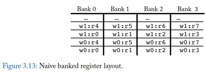
圖 3.13 顯示了每個 warp 的 register 到 logical bank 的簡單佈局。
- 在該圖中,warp 0 (w0) 中的 register r0 儲存在 Bank 0 的第一個位置,warp 0 中的 register r1 儲存在 Bank 1 的第一個位置,依此類推。
- 如果計算所需的 register 數量大於 logical bank 的數量,則 wrap around;例如,warp 0 的 register r4 儲存在 Bank 0 的第二個位置。
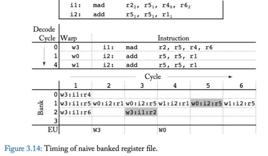
圖 3.14 展示了一個時序範例,突顯了此 microarchitecture 如何負面影響效能。
頂部顯示兩個指令,
- 第一條指令 i1 是 multiple-add operation,它從 register r5、r4 和 r6 讀取,這些 register 分配在 bank 1、0 和 2 中(圖中以下標表示)。
- 第二條指令 i2 是一條 addition instruction,它從在 bank 1 中的 register r5 和 r1 中讀取。
圖中的中間部分顯示了指令發射的順序。
- 在第 0 週期,warp 3 發出指令 i1,
- 在第 1 週期,warp 0 發出指令 i2,
- 在第 4 週期,warp 1 在由於 **bank conflict** 而延遲後發出指令 i2。
此圖的底部說明了不同指令存取不同 bank 的時序。
- 在周期 1,warp 3 中的指令 i1 能夠在周期 1 讀取其所有三個 source register,因為它們對應到不同的 logical banks(bank 1、0 和 2)。
- 但是,在周期 2,來自 warp 0 的指令 i2 只能讀取其兩個 source register 之一,因為它們都對應到 bank 1。
- 在周期 3,來自 warp 0 的指令 i2 的第二個 source register 讀取(bank 1)與來自 warp 3 指令 i1 的寫回(bank 2)平行執行。
- 在周期 4,來自 warp 1 的指令 i2 只能夠讀取第一個 source operand,因為兩者都對應到 bank 1。
- 在週期 5,來自 warp 1 的指令 i2 的第二個 source operand 不能從 register file 中讀取,因為該 bank 已經被 warp 0 較早發出的指令 i2 以較高優先權寫回存取。
- 最後,在周期 6 中,來自 warp 1 的 i2 的第二個 source operand 從 register file 中讀取。
::: info
總而言之,三個指令需要六個週期才能完成對其 source operand 的讀取,並且在此期間,許多 bank 都沒有被存取。
:::
### 使用 operand collector 的情況
### 3.3.1 OPERAND COLLECTOR
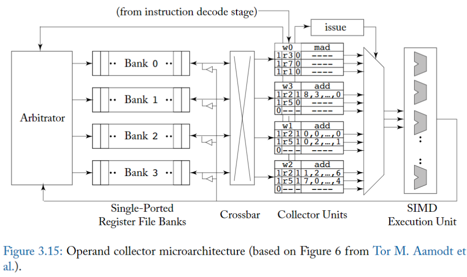
Operand Cellector microarchitecture 如圖 3.15 所示。
關鍵的變化是 「staging register 」已被「收集器單元 (collector unit)」 取代。
每條指令在進入 register 讀取階段時,都會被分配一個 collector unit。
- 每個 collector unit 包含執行指令所需的所有 source operand 的 buffer space。
有多個 collector unit,因此多個指令可以 overlap 讀取 source operand 的步驟
- 這有助於在各個指令的 source operand 之間存在 bank conflict 的情況下提高吞吐量。
- 多條 instruction 帶來更多 source operands,所以 arbiter 更有可能實現 更多的 bank-level parallelism,以允許平行存取多個 register file bank。
- **Arbiter's Role**: An arbiter 用來管理 access to the register file banks.
- Bank-level parallelism: 不同 banks 可以同時被不同 processors 或不同 instructions 存取。 對於平行處理來說可以提高性能。
- (補充) register read stage : read its source operands from the register file
**Operand collector 如何處理 bank conflict ?**
- 當 bank 衝突發生時,Operand collector 使用 scheduling 來應付。
**我們如何減少 bank 衝突數量的問題?**

圖 3.16 說明了 Coon 等人修改的 register layout,描述如何減少 bank conflict。
這個想法 **把 不同 warp 中的 equivalent registers (不同 thread 中,用途類似的 register) 分配到不同 bank**
例如在圖 3.16 中,warp 0 的 register r0 指派給 bank 0,但 warp 1 的 register r0 指派給 bank 1。
- 這並不能解決 「單一指令」的 register operand 之間的 bank conflict。
- 然而,它確實有助於減少 「來自不同 warp 的 instructions」之間的 bank conflict。
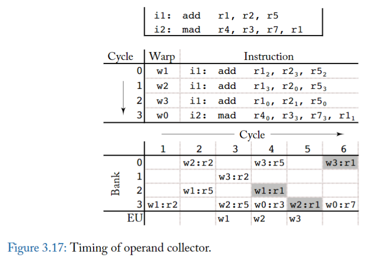
圖 3.17 顯示了一個 timing example,頂部顯示了一系列的加法和乘加指令。中間顯示了 issue 順序。
- 在周期 0 到 2 上發出來自 warp 1 到 3 的三個 i1 實例。
- 來自 warp 0 的指令 i2 的實例在週期 3 上發出。
值得注意的是,add 指令寫入的 register r1,在任何給定的 warp 下,r1 都和 source register r5 處於相同 bank
然而,與圖 3.13 中使用 register 佈局的情況不同,這裡 **不同的 warp 存取不同的 bank**,這有助於減少一個 warp 的寫回和讀取其他 warp 中的 source operand 之間的 conflict。
底部顯示了由於 operand collector 而產生的 bank-level timing access。
- 在周期 1 中,warp 1 中的 register r2 讀取 Bank 3。
- 在周期 4,注意
- warp 1 中的 register r1 進行寫回操作、
- warp 3 中的 register r5 進行讀取操作、
- warp 0 中的 register r3 進行讀取操作,三者平行進行。
### operand collector 的問題
由於它不會在準備 issue 不同指令的時間之間施加任何順序,因此它可能會出現先讀後寫(WAR) hazard [Mishkin et al ., 2016]。
**何時會發生?**
- 如果來自同一 warp 的兩個指令存在於 同一個 operand collector 中,而第一條指令會讀取第二條指令將寫入的 register
- 且,如果第一條指令的 source operand 存取遇到重複的 bank conflict,則第二條指令可能會在第一條指令讀取(正確的)舊值之前,將 new value 寫入 register 。
**如何防止?**
- 要求來自相同 warp 的指令,按照程式順序將 operand collector 留給 execution unit。
- 另外,有三種具有低硬體複雜性的潛在解決方案。
- 第一個是「release-on-commit warpboard」,提交時釋放 (release) 的 warpboard,每個 warp 最多允許執行一條指令。
- 這會對性能產生負面影響,在某些情況下,性能幾乎會降低兩倍。
- 第二個提議是「release-on-read warpboard」,讀取時釋放 warpboard,對於每個 warp,它每次只允許一個指令在 operand collector 中收集 operand。
- 該方案導致他們研究的工作負載最多降低 10%。
- 最後,為了在 operand collector 中實現 ILP,他們提出了一種 bloomboard 機制,該機制使用小型 bloom filter 來追蹤 ready 的 register 讀取(outstandung register reads)
- 相較於(錯誤地)允許 WAR 冒險,這導致的影響小於百分之幾。
- 另外,Gray 進行的一項分析表明,NVIDIA 的 Maxwell GPU 引入了一個“read dependency barrier”,由特殊的“control instruction”管理,可用於避免某些指令的 WAR hazzard
### 3.3.2 INSTRUCTION REPLAY: HANDLING STRUCTURAL HAZARDS
GPU pipeline 中存在許多潛在的 structural hazard,包含:
- **Memory Access**: If multiple threads try to access the same memory bank simultaneously and the bank can only service one request at a time, a structural hazard occurs. This can lead to bank conflicts
- **Register File Access**: If multiple processing units attempt to access the same register file at the same time, it can create a structural hazard.
- **Execution Units**: If more threads or warps are ready to execute than there are available execution units (like ALUs), this creates a structural hazard.
如果指令在 GPU pipeline 中真的遇到 structural hazard,會怎樣?
- 在 single-thread in-order CPU pipeline 中,標準解決方案是 stall 住較新的指令,直到遇到 stall condition 的那個指令又可以繼續執行,才讓新的指令可以繼續運行。
- 但這種方法在 highly multithreaded throughput 架構中不太理想。
- **Large Register File and Multiple Pipeline Stages**:
- 首先,考慮到數量很多的 Register Files 以及在複雜 pipeline 中分發 stall 訊號的複雜性,可能會影響 critical path (the sequence of stages that determines the total time to execute an instruction.)。因為需要引入額外的 buffer increasing area。
- 其次,停止其中一個 warp 的指令可能會導致來自其他 warp 的指令也在它後面停止。如果這些指令不需要導致停頓的指令所需的資源,整體 throughput 會受到影響。
為了避免這些問題,GPU 實作了一種指令重播 ( **instruction replay** ) 。
在一些 CPU 設計中發現了指令重播,根據具有 variable delay 的較早指令,推測性地 (speculatively) schedule 相關指令 ( dependency instruction )
- For example, a load instruction might hit or miss in a first-level cache, and the latency of this operation can vary.
- These CPUs might speculatively "wake up" dependent instructions <u> based on the assumption of a cache hit </u> to improve single-threaded performance.
- If the speculation turns out to be incorrect (e.g., a cache miss occurs), instruction replay is used to re-execute the dependent instructions correctly.
相比之下,GPU 避免推測,因為它往往會浪費能源並降低 throughput。相反,在 GPU 中使用 instruction replay
- 以避免阻塞 pipeline 和電路區域
- 避免因停頓而導致的時序開銷。
為了實現指令重播,GPU 可以將指令保存在 instruction buffer 中,直到知道它們已完成或指令的所有單獨部分都已執行 [Lindholm et al., 2015]。
## 3.4 RESEARCH DIRECTIONS ON BRANCH DIVERGENCE
在 warp 中,最理想的情況是每個 thread 都執行相同的 control flow path
這樣 GPU 就能在 SIMD HW 上 execute them in lockstep (perform operations simultaneously and synchronously)
review:
- Branch divergence occurs when threads within the same warp need to take different execution paths due to conditional branching in the code.
- This can lead to inefficiencies because the warp must execute each branch path serially, reducing the parallel efficiency.
關鍵問題: 如果在面對 branch divergence 時,只用 baseline 的 SIMT stack 方式
會有以下缺點
1. 較低的 SIMD 效率: 因為 SIMT stack 會 serialize 不同 branch target 的 execution,所以每次只會有一部分的 thread 真正在工作,出現其他 thread idle / SIMD HW idle 的情況
2. 不必要的 serialization: 因為 warp 內的 threads 之間並沒有 data dependency 的特性,他們之間主要透過 shared memory 和 barrier 來溝通。所以 GPU 理論上可以在排程中,間隔安排使用不同 diverged warps
3. 不妥的 MIMD: baseline 的 SIMT stack 中,diverged warps 會被要求在 compiler 定義的 reconvergence point 中進行會合,這代表隱性的在 reconvergence point 中,每個 warp 也會出現 synchronization point。這種隱性的 synchronization,可能會和使用者自訂的 synchronization 機制搞混在一起,導致 warp deadlock
4. 面積成本: 每個 SIMT stack 在 each warp 中會需要佔據一定比例的面積 ( e.g. 32x64 bits ),如果 in-flight warps ( active warps at given time ) 越多,這個數量就越大;潛在的機會成本就是用做其他元件的空間及其帶來的 throughput 提升,例如 更大的 cache,更多 ALU。
後略...
# SIMT Core 各個 component 簡介
## 1.1.1 Fetch
Fetch unit 是個 scheduler,
- 對於一個 warp,如果在 I-Buffer 中沒有任何 valid 指令,那麼這個 warp 就可以用 RR 方式進行 instruction fetch。
- 預設情況下,一個 warp 的兩個連續的指令被取出。
- `gpgpu_max_insn_issue_per_warp` 來控制
- 一旦 Warp 被選中,會發送 read request 到 I-Cache 中取指令,**request 的 target address 是 "該 warp 的 next instruction**"
- 合法的 warps 會用 round robin 的方式來存取 I-Cache
- 當 warp 成功排程並在 Fetch 取到一個 warp 的指令後,I-Buffer 中對應的 entry valid bit 為 1,數值維持直到該 Warp 所有取到的指令均執行完畢(這些指令都送到了execution pipeline) 才會改變
## 1.1.2 Decode, I-Buffer
I-Buffer is initially empty with all valid bits and ready bits deactivated
一條指令從 instruction cache fetch 出來後會進行解碼,然後存入 instruction buffer (I-Buffer)。
- 每個 warp 有兩個 I-Buffer entry
- 每一條 I-Buffer entry 的三個欄位如下: valid bit, ready bit 和 single decoded instruction for this warp
- Valid bit (1 bit): Valid bit 為1表示這個 warp 在 I-Buffer 中還存在著未送出的指令
- Valid bit 主要是和 Fetch 單元進行交互,如果一個 warp 在 I-Buffer 中還有未送出的指令 (Valid bit 為1),那麼就不會進行指令 fetch 的操作
- Ready bit (1 bit): Ready bit 為1表示這個 warp 的這條 decoded instruction 已經可以送出到 execution pipeline,
- 是否 Ready 由 Scoreboard, Operand Unit 等機制在 schedule and issue stage 階段來決定
- 具體何時送出由 warp scheduler 以及 scheduling policy 決定
- 單一個 decoded instruction
- Decode 單元一次解碼2條指令,解碼後的指令 fill 到 I-Buffer 中
## 1.1.3 I-Cache
instruction cache 是 read-only, non-blocking set-associative cache, 可以使用 FIFO 或是 LRU 替換策略,搭配 on-miss 或是 on-fill 分配策略。
對 I-Cache 的 request 可能會得到3種狀態: hit, miss or reservation fail.
reservation fail
- 如果 miss status holding register (MSHR) 已滿或 cache set 中沒有可替換的區塊,則會導致 reservation fail。
- 因為所有 block 都被先前的 pending request 佔據 (細節在2.3.4的 cache 部分)。
在 hit 和 miss 情況下,round robin fetch scheduler 都會移動到下一個 warp。
- 對於 hit, fetched 指令送到 decode stage. 開始解碼
- 對於 miss, instruction cache 會產生一個 request 。
- 當接收到 miss response, 會將該 cache block 填入 instruction cache, warp 會再次存取 instruction cache.
- 當 miss 仍在等待 (pending), warp 不會存取 instruction cache
> 這點對應原始碼 hader_core_ctx::fetch 函式中,需要 access_ready 才存取指令 cache,否則就去找下一個 I-Buffer 有空間、指令 cache 沒有等待 Miss 等待的 active warp
如果 warp 的所有 thread 都已完成執行而沒有任何 outstanding stores or pending writes to local registers, 則 warp 執行完成並且不再被 fetch scheduler 考慮。
- The thread block is considered done once all warps within it are finished and have no pending operations.
- Once all thread blocks dispatched at a kernel launch finish, then this kernel is considered done.
- Outstanding store: store (write) memory operations issued by threads that have not yet been completed or committed to memory.
在 decode stage, recent fetched 指令會被解碼並存入相應的 I-Buffer entry 等待被送出。
## 1.2 Instruction Issue
第二個 round robin scheduler (issue 單元) 選擇 I-Buffer 中的一個 warp 將其送出到pipeline。
這個 round robin scheduler (issue) 和用於 schedule instruction cache 存取的 round robin scheduler (fetch) 分開。issue scheduler 可以配置成每個週期送出相同 warp 的多條指令。
當前正在檢查的 warp 中,若每條 valid 指令 (解碼後未送出的指令) 滿足以下條件時有資格被送出 (即: eligible warp)
- warp 沒有在等待 barrier
- I-Buffer 中有 valid instructions (valit bit is set)
- 通過了 scoreboard 檢查
- instruction pipeline 中的 operand access stage 沒有 stall
記憶體指令 (Load, store, memory barriers) 送出到 memory pipeline。
其他指令可以使用 SP (stream processor) 和 SFU pipeline,不過通常會去 SP pipeline。
- 然而,如果有control hazard, I-Buffer 中的指令會被刷掉(flush).
順利送出指令到 pipeline 後**會更新 warp 的PC,將其指向下一條指令**(假設所有分支not-taken).
- GPU 是有 memory pipeline和 ALU pipeline的,兩種類型的指令由不同的硬體單元執行
在 issue stage 會執行 barrier 操作。同樣,會更新 SIMT stack 以及追蹤 register dependency (scoreboard). warp 在 issue stage 會等待 barrier (__syncthreads())
## 1.3 SIMT Stack
SIMT Stack 是每個 warp 都有的資源。
SIMT Stack 用於處理 SIMT 架構的分支問題 (branch divergence).
因為 GPU 中 divergence 會降低 SIMT 架構的效率,所以有很多降低分支危害的技術。
其中最簡單的技術是 post-dominator stack-based reconvergence mechanism.
這個技術在最早的保證聚合點 (guaranteed reconvergence point) 來同步分支,以提高 SIMT 架構的效率。 GPGPU-Sim 3.x 使用了這個機制。
- SIMT Stack entry 代表不同的 divergence level。在每遇到一個 divergence branch,一個新的 entry push 到 stack 上方。
- 到達聚合點時 stack top 的 entry 出 stack 。
- 每個 entry 會儲存
- 新分支的target PC、
- the immediate post dominator reconvergence PC (也就是聚合點PC) 、
- 發散到該分支的 thread 的 active mask。
- 在這個模型中,每個 warp 的SIMT Stack在每條指令送出後更新。
- 沒有分支的 target PC 會正常更新為 next PC.
- 有分支的情況下,entry 會 push 入stack,entry 包含新的 target PC、對應的 thread active mask、the immediate post dominator reconvergence PC
- **因此,如果 SIMT Stack stack top 的 next PC 不等於目前正在檢查的指令的 PC,則偵測到 control hazard。 (也就是跳轉錯誤)**
NVIDIA and AMD 實際上使用特殊指令修改了他們的 divergence stack 的內容。這些 divergence stack 指令未在 PTX 中公開,但在實際硬體 SASS 指令集中可見(使用 decuda 或 NVIDIA 的 cuobjdump 可見)。若當前版本的 GPGPU-Sim 3.x 被配置為透過 PTXPlus 執行 SASS(參見 PTX 與 PTXPlus)時,它會忽略這些低階指令,而是建立一個類似的控制流程圖來識別 immediate post-dominators。我們計劃在 GPGPU-Sim 3.x 的未來版本中支援低階分支指令的執行。
## 1.4 Scoreboard
Scoreboard 演算法檢查 WAW 和 RAW dependency 。
- 在 issue stage 會保留 「被 warp 寫入的 register」。
- Scoreboard 演算法透過 warp ID 進行索引。
- 它將「使用到的 register number」 存入「與 warp ID 對應的 entry中」。
- 保留的register在 write back stage 被釋放。
先前提到,一個 warp 的解碼指令在 Scoreboard 判斷其沒有 WAW 和 RAW hazards 後才可以被 schedule for issue。而 Scoreboard 會藉由觀察 register,是否會被前面一條已經送出的指令寫入(但是該指令目前尚未將結果寫回register file),以此來偵測 WAW 和 RAW 危害。
# Register Access and the Operand Collector
許多 NVIDIA 的專利描述了一種稱為 Operand Collector 的結構。
Operand Collector 是一個 set of buffers,其判斷邏輯使用 multiple banks of single ported RAMs 來挑選「multiported register file」
這個設計能夠節省能量和面積,對於吞吐量的提升很重要。
指令解碼後,一種稱為 Collector Unit 的硬體單元被指派用於 buffer 該指令的 source operands
Collector Unit 並非透過 register renaming 來消除 dependency ,而是在時間上分隔register operand 的存取,使得在單一 cycle 中對 bank 的存取不超過一次。

在圖示中,每個Collector Unit 有3個 operand entry.
- 每個entry 有4個欄位
- a valid bit
- a register identifier
- a ready bit
- operand data.
- operand data 欄位有128B,可以容納32個4B元素(warp 中每個 thread 4B,總共32個 thread ,剛好放下一個 warp)。
另外,Collector Unit 還存有「指令屬於哪個 warp」 的資訊。
對於每個 bank, arbitrator 包含一個 read request queue for each bank 來保證存取操作不衝突。
當一條指令從 decode stage 傳過來,會為這條指令分配一個 Collector Unit, 並把 operand, warp, register identifier, valid bit 都 set 起來.
arbitrator 會將 source operand 的read requests queued in the arbiter。為了簡化設計,執行單元的寫回 request 總是優先於 read requests。
arbitrator 選擇最多4個 (圖中硬體是4個 bank, 實際上可能有32個或更多) 不衝突的存取 request 傳送到register file。為了減少 crossbar 和 Collector Unit 的面積,每個 Collector Unit 每週期只接受一個 operand 。
當從 register file 中讀到 operand 並放入對應的 Collector Unit, 就將 ready bit 置1. 當一條指令的所有 operand 都 ready,那麼指令就可以送出到 SIMD 執行單元。
在這個模型中,每個後端 pipeline (SP, SFU, MEM) 有一組專用的 Collector Unit, 他們共享一個通用的Collector Unit pool. 每個 pipeline 可用的 units 數量和 general units 的容量都是可配置的。
# ALU Pipeline
GPGPU-Sim v3.x 建模了兩種 ALU 函數單元
- SP 單元 executes all types of ALU instructions except transcendentals.
- SFU 單元 executes transcendental instructions (Sine, Cosine, Log... etc.).
兩種單元都是pipeline化以及 SIMD 類型。
- SP 單元通常每週期執行一個 warp 指令,
- SFU 可能是幾個週期執行一個 warp 指令。例如 sine 指令的執行需要4個週期,倒數指令需要2個週期。不同類型的指令有不同的執行延遲。
> 可以看到 Fermi 架構中,一個 SM 有32個 SP, 也就是圖中的 CUDA Core, 有4個 SFU, 16個 LDST Unit 用來處理記憶體指令。這個數量是依照實際使用中不同類型指令的大概比例決定的。
每個 SIMT Core 都有 SP 和 SFU 單元。每個單元都有來自 operand collector 的 independent issue port 。這兩個單元 (SP, SFU) 共享同一個「connects to a common writeback stage 的 output pipeline register」。在 operand collector 的 output 有一個 result bus allocator,以確保 units 永遠不會因為 shared writeback 而 stall。每個指令在發出到任何一個 units 之前,都需要在 result bus 中分配一個 cycle slot。注意記憶體pipeline有它自己的writeback stage,不由這個 result bus allocator 管理。
> 也就是 memory pipeline 和 execution pipeline 從不同的地方寫回,下一節會介紹 memory pipeline
# Memory Pipeline (LDST unit)
GPGPU-Sim支援CUDA中的各種記憶體空間,在PTX中可見。
在這個模型中,每個 SIMT core 有4個不同的片上 L1 記憶體:
- shared memory,
- data cache,
- constant cache,
- texture cache。
下表顯示了哪些晶片記憶體服務於哪種類型的記憶體訪問

儘管它們被建模為獨立的物理結構,但它們都是 memory pipeline (LDST Unit) 的組件,因此它們都共享相同的writeback stage。下面描述了這些空間是如何運作的
- Texture Memory: Texture Memory的 cache 在 L1 texture cache 中(僅為 Texture access 預留),也 cache 在 L2 cache 中 (如果有啟用的化)。
- GPU上的執行緒無法寫入紋理記憶體空間,因為 L1 texture cache 是唯讀的。
- Shared Memory: 每個 SIMT core 都包含一個可配置數量的共享 scratchpad memory, thread block 中的 thread 可以共享這些 memory。這個記憶體空間不受任何 L2 的支持,由程式設計師顯式地管理。
- 在 CUDA 程式設計中使用 `__shared__` 為變數分配共享記憶體以優化效能
- Constant Memory: 常數和參數記憶體 cache 在唯讀的 Constant Memory 中。
- Parameter Memory: 同上
- Local Memory: cache 在 L1 data cache 中,也支援 L2 cache.
- Local Memory 不能共用 local data.
- Local Memory 的 L1 data cache write policy 和 Global Memory 不同,其他的機制相同。
- Global Memory: global 和 local 存取都由 L1 data cache 提供。依照CUDA 3.1程式設計指南的描述,來自同一個 warp 的 scalar thread 的存取是以 half-warp 為基礎合併的。
- The memory subsystem can process these coalesced accesses **at a rate of 2** per SIMT core cycle.
- If a memory instruction generates more than 2 accesses, these additional accesses will be processed at a rate of 2 per cycle.
- 也就是說我們希望一個half-warp 的16個 thread 可以完美地進行coalesced memory access, **16個 thread 都訪問同一個cache line, 這樣只需要進行1次memory access.** 然後一個週期進行2次half-warp access . 這樣最好情況下1個SIMT core cycle 可以完成一個warp 的記憶體指令。
- 但對於一些記憶體指令可能會產生32次 accesses (最壞情況下),那麼這樣其實需要16個 SIMT core cycles 來完成這條記憶體指令
## 4.1 L1 Data Cache
private, per-SIMT core, non-blocking, 為 local and global memory access 提供服務。
- L1 Cache 沒有劃分為 bank,
- 每個 SIMT core cycle 可以為2個 coalesced memory request 提供服務 (如上所說)。
- 一個傳入的記憶體 request 不能跨越兩條 L1 data cache line。 (也就是1個 SIMT core cycle 支援2次 access)
- 也要注意 L1 data cache 不是一致的 (not coherent, 不具備 cache coherence)
The table below summarizes the write policies for the L1 data cache.

對於 Local Memroy, L1 data cache 使用 write-back cache with write no-allocate。
- (cache hit) write-back 會先將資料寫入cache中,然後再將同一位址的資料整批一起寫入主記憶體中(非立即寫入,等到要被驅逐時才寫入)
- (cache miss) write no-allocate: 會直接將資料寫到主記憶體中,不會再從記憶體中載入到cache
對於 Global Memory, write hits會導致 cache block 被驅逐
- 這模擬了 PTX ISA 規格中概述的 global stores 的預設策略。
L1 data cache hit 的 Memory accesses 在一個 SIMT core cycle 內會得到服務。
而未 hit 的訪問(Missed accesses) 被插入到 FIFO miss queue 中。
- 每個 SIMT core cycle 會由 L1 data cache 產生一個 fill request(假定 interconnection injection buffers 能夠接受 request )。
- cache 使用 Miss Status Holding Registers 來保留正在處理的 miss request 的狀態。它們是一個fully-associative array 。
- 當一個 request 正在運行時,對 memory system 的 Redundant accesses 被合併到 MSHRs 中。 MSHR table 有固定數量的 MSHR entry。每個 MSHR entry 可以幫 single cache line 來處理固定數量 的miss requests。
- cache misses 的 memory request 被加入 MSHR,如果這個 cache line 沒有 pending request,則產生一個 fill request 。當 cache 的 fill request 被回應,cache line 被插入 cache 中,對應的 MSHR entry 被標記為 filled 狀態。針對 filled MSHR entry 的 request ,每周期會回復一個 response。一旦 filled MSHR entry 中的所有 request 都被回應,就可以釋放這個 MSHR entry.
- MSHR entry 的數量和每個 entry 的最大 request 數是可設定的。
## 4.1.1 MSHR (Miss Status Holding Registers)
> On a cache hit, a request will be served by sending data to the register file immediately. On a cache miss, the miss handling logic will first check the miss status holding register (MSHR) to see if the sang reem 獎外 15 ones. If so, this request will be merged into the same entry and no new data request needs to be issued. Otherwise, a new MSHR entry and cache line will be reserved for ability data request. Aache stache on cache cache stail events such as when there are no free MSHR entries, all cache blocks in that set have been reserved but still haven't been filled, the miss queue is full, etc.
request 發生 miss 時,會先查看 MSHR 中相同 cache request 是否已經存在。
- 如果存在則合併request (也就是忽略了這次的 request )。
- 如果不在 MSHR 中,則將這條 cache line request 加入 MSHR entry,且這條 cache line 被置為 reserved 狀態。將該 request 資料放入 miss queue,排隊向下一層 cache 發送 data request。
- 如果 MSHR entry 滿了,也就是 request 資料的所有 cache blocks 已經被置為 reserved 狀態,或是 miss queue is full,cache status handler may fail on resource unavailability.
MSHR entry 記錄
- cache block address,
- block offset,
- associated register
MSHR相當於一個大小固定的陣列,用於存放所 request 資料尚未返回L1 cache中的miss request 。當資料返回L1 cache 後,即從MSHR中刪除所對應的miss request 。
發生 memory access miss 後,如果 cache line 沒有 pending request ,那麼 cache line 就會發送 fill request。當 fill response 回來後,將其插入 cache,對應的 MSHR entry 會標記為 filled 狀態。每週期回應 filled MSHR entry 的一個 request 。當 filled MSHR entry 中的所有 request 都被回應,MSHR entry is freed.
## 4.2 Texture Cache
The texture cache model is a **prefetching texture cache**.
texture memory 大多數存取都有 空間局部性,效果最好的是 16KB。在現實的圖形使用場景中,許多 Texture cache 存取會 miss。在DRAM中存取 Texture 的延遲大約是100個週期。特點是記憶體存取延遲比較大而 small cache size,因此何時在 cache 中分配 line 這個問題至關重要。 prefetching texture cache 透過將 cache tag 的狀態和 cache blocks 的狀態 分開來解決這個問題。
- tag array 表示在100個週期後 miss 被服務後的 cache 將處於的狀態。
- data array 表示 miss 服務完成後的狀態。
- 實現這種解耦的關鍵是使用 reorder buffer,以確保傳回的 Texture miss data 以 tag array 存取的相同順序放置到 data array 中。
## 4.3 Constant (Read only) Cache
對常數和參數記憶體的存取透過 L1 constant cache 運行。這個 cache 是用一個 tag array 實現的,就像 L1 data cache ,只是它不能被寫入。
### Thread Block / CTA / Work Group Scheduling
Thread Block, CTA 是 CUDA 中的術語,Work Group 是 OpenCl 中的術語,一次會送出一個 block 到 SIMT core。每個SIMT clock cycle, block 送出機制會以輪詢機制挑選block 送出到SIMT Core Clusters. 對於每個被選擇的SIMT Core Clusters, 如果SIMT core 上有足夠的空閒資源,那麼將從選定的kernel 向該SIMT core 發出單一block。
對 CUDA 程式設計有了解應該很熟悉 grid, block, thread 的概念
如果應用程式中使用了多個 CUDA Streams 或命令佇列,那麼多個 kernel 可以在GPGPU-Sim 中並發執行。不同的 kernel 可以跨不同的 SIMT core 執行。單一 SIMT Core 一次執行1個 kernel 中的 blcoks。如果多個 kernel 同時執行,那麼選擇向每個 SIMT Core 發出的 kernel 也是輪詢的。在 CUDA 架構上的並發 kernel 執行是在 NVIDIA CUDA Programming Guide 中描述的
這部分內容是 CUDA 程式設計中的細節
### Interconnection Network
SIMT Core Cluster 之間不會直接與對方通信,因此在 interconnection network 中沒有 coherence 通道,只有4種 packet types
-Read-request
-Write-request from SIMT Core to Memory Partition
-Read-replys
-Write-acknowledges sent from Memory Partition to SIMT Core Clusters
# Reference:
- Aamodt, T. M., Fung, W. W. L., & Rogers, T. G. (2018). General-Purpose Graphics Processor Architectures. Morgan & Claypool Publishers.
- Hwu, W. W., Kirk, D. B., El Hajj, I. (2023). Programming Massively Parallel Processors: A Hands-on Approach. Morgan Kaufmann.
- [CUDA 笔记:GPU 架构中 Predicate Register - 知乎](https://zhuanlan.zhihu.com/p/614351020)
- [Instruction-Level Parallelism - Algorithmica](https://en.algorithmica.org/hpc/pipelining/)
- [章節.3 指令階層架構平行與其利用 - Learning Lounge (tobygao.github.io)](https://tobygao.github.io/Learning-Lounge/2018/05/07/ca-3-ilp.html)
- [Inside Volta: The World’s Most Advanced Data Center GPU | NVIDIA Technical Blog](https://developer.nvidia.com/blog/inside-volta/)
- [GPGPU-Sim 3.x Manual](http://gpgpu-sim.org/manual/index.php/Main_Page#SIMT_Cores)
 Sign in with Wallet
 Sign in with Wallet