# Ch4 Memory System
## Memory hierarchy 介紹
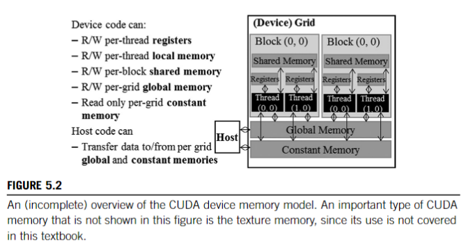
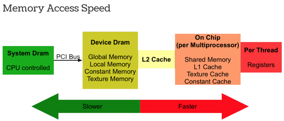
CUDA-capable GPUs have a memory hierarchy as depicted in Figure 4.

The following memories are exposed by the GPU architecture:
- **Registers**—These are private to each thread, which means that registers assigned to a thread are not visible to other threads. The compiler makes decisions about register utilization.
- **L1/Shared memory**—Every SM has a fast, on-chip scratchpad memory that can be used as L1 cache and shared memory.
- The shared memory is partitioned among the thread blocks that are concurrently running on an SM.
- All threads within a single thread block can access the shared memory allocated to that block.
- Different thread blocks, even if they are running on the same SM, cannot access each other's shared memory.
- Shared memory is an efficient means by which threads can cooperate by sharing their input data and intermediate results.
- **Read-only memory**—Each SM has an instruction cache, constant memory, texture memory and RO cache, which is read-only to kernel code.
- **L2 cache**—The L2 cache is shared across all SMs, so every thread in every CUDA block can access this memory. The NVIDIA A100 GPU has increased the L2 cache size to 40 MB as compared to 6 MB in V100 GPUs.
- **Global memory**—This is the framebuffer size of the GPU and DRAM sitting in the GPU.
- **Local memory**—The local memory is actually placed in global memory and has similar access latency, but it is not shared across threads.
- Each thread has its own section of global memory that it uses as its own private local memory where it places data that is private to the thread but cannot be allocated in registers.
- This data includes statically allocated arrays, spilled registers, and other elements of the thread’s call stack.
### Device memory model

CPU 通常包含兩個獨立的記憶體空間:register file 和 memory
而現代 GPU 在邏輯上將記憶體進一步細分為局部 (local) 和全域 (global) 記憶體空間。
- 局部記憶體 (local memory) 空間是每個 thread 專用的,通常在 register spilling 出現時使用
- 全域記憶體 (global memory) 用於在多個 thread 之間共享的資料結構。
此外,現代 GPU 實作了要由 programmer 來管理的 **scratchpad memory**,這塊 memory 在 cooperative thread array, CTA(_thread block_ in CUDA) 中一起執行的 thread 之間能夠共享存取 (shared access)。
要創造出這塊 shared memory 的原因是:
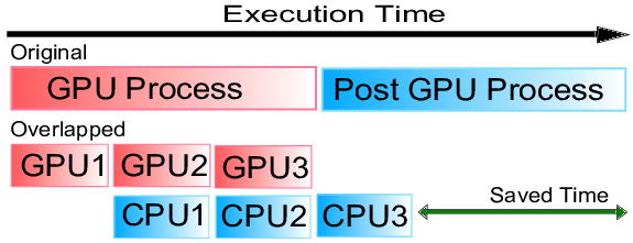
1. **Overlap of Memory Access and Computation**
在許多應用程式中,programmer 知道在計算中的給定步驟需要存取哪些資料。
透過一次將所有這些資料載入到 shared memory 中,由於
- shared memory 屬於 on-chip,存取速度較快
- 一次處理大量資料,比又少又慢的獨立存取 global memory 有效率,因為每次 GPU 要去 off-chip 的 memory 拿資料,core 就會 idle
所以這麼做的話,GPU 一方面可以用較快的 shared memory 中的 data 進行計算,一方面可以處理較慢的 off-chip 的 memory transfer。( Concurrently )
- 即:GPU 可以 overlap 延遲長的 off-chip memory access,並在對這些資料執行計算時,避免對記憶體的長延遲存取( 因為 shared memory 比較快)
- **overlapping 示意圖:**
- 
2. **Lower energy consumption**
在給定的時間內,DRAM bandwidth(the number of bytes that can be transferred between the GPU and off-chip memory in a given amount of time)相對於在相同時間內可以執行的指令數來說 是很小的。
同時,在 off-chip memory 和 GPU 之間傳輸資料所消耗的能量,比從 on-chip 記憶體存取資料所消耗的能量高幾個數量級。因此,從 on-chip 記憶體存取資料會更節省能源。
我們將記憶體系統的討論分為兩部分,將記憶體劃分為駐留在 GPU core 中的部分,和連接到 off-chip DRAM 晶片的記憶體分區 (memory partition) 中的部分。
::: success
GPU 上不同 memory 的整理!
:::

|MEMORY|ACCESS|SCOPE|LIFETIME|SPEED|NOTE|
|---|---|---|---|---|---|
|Global|RW|All threads and CPU|All|Slow, cached|Large, DRAM|
|Constant|R|All threads and CPU|All|Slow, cached|Read same address|
|Local|RW|Per thread|Thread|Slow, cached|Register Spilling|
|Shared|RW|Per block|Block|Fast|Fast communication between threads|
|Registers|RW|Per thread|Thread|Fast|SRAM, High Bandwidth|
- In a typical device, the aggregated access bandwidth of all the register files across all the SMs is at least two orders of magnitude higher than that of the global memory.
- register file vs global memory
1. lower latency
2. higher throughput
3. fewer instructions when accessing。原因: global memory 多了一個 load 指令;而且處理器在每個 cycle 可以抓的指令數有限;能源效率
- shared memory 也是需要用 load 指令,但因為他 on-chip,所以
- 延遲 => global>share>register
- throughput: => global < share < register
- 同一個 block 都是在同一個 SM 上面執行,且,Shared memory是構建在SM 上,再分割給每一個 block
- 所以在同一個SM的前提下 threads 可以在不同 cores 上執行,Shared memory的實作也支援不同的 core 能夠同時存取其資料

---
## 4.1 FIRST-LEVEL MEMORY STRUCTURES
主要介紹:
- **unified L1 data cache** 和 **scratchpad memory(shared memory)** 以及它們如何與 core 的 pipeline 互動。
- The Unified L1 data cache refers to a type of cache memory architecture used in some GPUs (Graphics Processing Units), particularly those designed by NVIDIA starting with their Fermi architecture. In a unified cache architecture, **the L1 cache is shared between different types of data rather than being dedicated to a specific type (such as textures or shader instructions)**. This approach contrasts with separate caches for different data types, which was common in earlier GPU designs.
- L1 texture cache 的典型微架構。雖然它在 GPU 運算應用程式中的使用有限,但它提供了一些關於 GPU 與 CPU 有何不同的見解。
- 最近的一項專利描述如何統一 texture cache 和 L1 data(例如,在 NVIDIA 的 Maxwell 和 Pascal GPU 中發現的)[Heinrich et al., 2017]。
- GPU 中一級記憶體結構在遇到 hazard 時,可以透過重播指令 (replaying instruction) 來和 core pipeline 互動。
- 擴展了先前對 replay 的討論,並專注於記憶體系統中的 hazard。
### 4.1.1 SCRATCHPAD MEMORY AND L1 DATA CACHE
在 CUDA 程式設計模型中,「shared memory」是指相對較小的記憶體空間,低延遲,且在給定 CTA(即 thread block)內的所有 thread 都可以存取。
- 在其他架構中,這樣的記憶體空間有時被稱為 scratchpad memory
- 存取此記憶體空間的低延遲,通常與 register file access 的延遲差不多。
- 事實上,早期的 NVIDIA 專利將 CUDA「 shared memory (shared memory)」稱為 global register files [Acocella and Goudy, 2010]。
- 在 OpenCL 中,這個記憶體空間被稱為「局部記憶體 (local memory)」。
從程式設計師的角度來看,使用 shared memory 時要考慮的因素:
1. 超出其有限的容量,
2. 可能發生 bank conflict
- 因為每個 thread 都可以存取所有的 bank。當多個 threads 在給定週期中存取同一個 bank 並且 threads 希望存取該 bank 中的不同位置時,就會出現 bank conflict。
具體來說,shared memory 被實作為 SRAM,並且在一些專利 [Minkin et al., 2012] 中被描述為
- 每個通路(lane) 具有一個 bank,
- 每個 bank 具有一個讀端口和一個寫端口(即:1R1W)
**L1 data cache?**
The L1 cache stores frequently accessed data from the global memory to reduce access times and improve overall performance.
在某些架構中,L1 cache 僅包含沒有被 kernel 修改的位置,這有助於避免 GPU 上缺乏 cache coherence 而導致的複雜性。
**Coalesced**
從程式設計師的角度來看,存取 global memory 時的一個關鍵考慮因素是,給定 warp 中不同 threads 存取的記憶體位置之間的關係。
- 如果 warp 中的 **所有 thread 都存取位在同一個 L1 data cache block 內的位置**,且該區塊不存在於 cache 中,則只需將 **單一請求** 傳送到較低層級的 cache。這種存取被稱為「coalesced」。
- 如果 warp 中的 threads 存取不同的 cache block,則需要產生 **多個記憶體存取**。此類存取被稱為 uncoalesced。
程式設計師應該要避免 bank conflict 和 uncoalesced 的存取,但為了簡化硬體寫程式的麻煩,兩者在硬體中都是允許的。

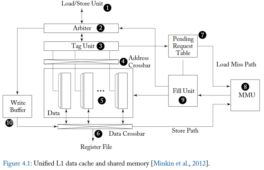
圖中的設計實現了 unified shared memory 和 L1 data cache,這是 NVIDIA 的 Fermi 架構中引入的功能,也存在於 Kepler 架構中。圖的中心是一個 **SRAM data array (5)**,它可以配置為「部分用於 share memory 的 direct memory access,部分用於 set associative cache」。
> 此設計透過在處理 bank conflict 和 L1 data cache misses 時使用重播機制 (replay mechanism) 來支援與 instrution pipeline 的 non-stalling 介面。
為了幫助解釋這種 cache 架構的操作,我們首先考慮
1. 如何處理 shared memory accesses,
2. 然後考慮 coalesced cache hits,
3. 最後考慮 cache misses 和 uncoalesced accesses。
對於所有情況,
- 首先從 instrution pipeline 內的 load/store 單元 (1) 向 L1 cache 發送 memory access request。
- 一個 memory access request 由一組 memory addresses 組成,warp 中的每個 thread 對應一個 memory address 及 operation type
- 接著進入 arbiter,處理 **Shared Memory Access Operations**
- 對於 shared memory accesses,**arbiter 會確定 warp 中的 requested address 是否會導致 bank conflict。**
- Bank conflicts occur when multiple threads attempt to access data from the same memory bank simultaneously, leading to delays.
- 如果 request 的 address 會導致一個或多個 bank conflict,arbiter 會將 request 分成兩部分。
- 第一部分包括 warp 中沒有 bank conflict 的 thread 子集的位址。
- 這部分的 original request 被 arbiter 接受,以便 cache 進一步處理。
- 第二部分包含導致與第一部分中的位址發生 bank conflict 的位址。這部分 original request 返回 instrution pipeline,且必須再次執行。隨後的執行稱為「**重播 (replay)**」。
而要在哪裡儲存 original shared memory request 的 replay 部分,是需要討論 tradeoff 的。
- 雖然可以透過從 instruction buffer 重播(replay) memory access instruction 來節省 area,但存取大型 register files 時更消耗能量。
- 能源效率的更好替代方案可能是,在 load/store 單元中為 replay memory access instructions 這個動作提供有限的 buffer,並避免在該 limited buffer 沒有 free space 時就從 instruction buffer 中 schedule memory access instructions。
在考慮 replay request 會發生什麼之前,讓我們考慮 **如何處理已接受的記憶體請求部分**。
- 由於 shared memory 是 directly mapped 的,data 已經存在 cache 中,因此 shared memory request 的已接受部分可以繞過 (bypass) tag unit (3) 中的 tag lookup(查找)。
- 當 arbiter 接受到一個 shared memory load 請求時,它將寫回事件(writeback event) schedule 到 instrution pipeline 內的 register file (這是pipeline 的 final stage 了)。而這個動作因為沒有 bank conflict,所以 DMA lookup 的 latency 是比較固定的(more predictable)。
- Arbiter's Role: In a GPU, an arbiter is responsible for managing access to shared resources like memory. When a shared memory load request is made, the arbiter plays a crucial role in controlling and scheduling this access.
- tag unit 決定每個 thread 的請求對應到哪個 bank,以控制 address crossbar (4),這個 address crossbar 將位址指派給 data array 中的各個 bank。
- data array(5) 中的每個 bank 都是 32 bit 位元寬,並且具有自己的解碼器,允許獨立存取每個 bank 中的不同 row。
- 資料透過 data crossbar (6) 返回到對應 thread 的 lanes 以儲存在 register files 中。只有與 warp 中的 active threads 對應的 lane 才會將值寫入 register file。
**如何處理 rejected 的記憶體請求部分**
假設 shared memory lookup 為 single-cycle latency,shared memory request 的 replay 部分可以在其 accepted portion 之後的那個 cycle 來存取 L1 cache arbiter。
- 如果這個 replay 部分遇到 bank conflict,它又會進一步細分為 accepted 和 replayed 部分。
### Cache Read Operations
:::success
接下來,讓我們考慮如何處理 load global memory
:::

由於 global memory 只有一部分被 cache 在 L1 中,因此 tag unit 將需要檢查資料是否存在於 cache 中。
雖然 data array 被切分為多個 bank 以使各個 warp 能夠靈活地存取 shared memory,但對於 global memory,使用上僅限於每個 cycle 存取單個 cache block。
原因:
- 這種限制有助於減少 tag storage overhead,
- 也因為這是使用標準 DRAM 晶片標準介面。
在 Fermi 和 Kepler 中,L1 cache block 大小為 128 bytes,在 Maxwell 和 Pascal [NVIDIA Corp.] 中進一步分為四個 32 bytes 的磁區 (sector) [Liptay, 1968]。 32 bytes 磁區大小對應於可以在單一存取中從最近的圖形 DRAM 晶片(例如 GDDR5)中讀取的最小的 data size。每個 128 bytes 的 cache block 由 32 個 bank 中同一列中的 32 bit 寬的 entry 組成。
Load/store 單元 (1) 會計算 memory addresses,並套用 coalescing rules 以將 warp 的 memory access 分解為單獨的合併存取 (coalesced access),然後將其饋送到 arbiter (2)。
- 如果沒有足夠的資源可用,
- 例如,如果存取映射到的 cache set 中的所有 way 都忙,
- 或者在 pending request table (7) 中沒有空閒 entry。arbiter 可能會拒絕請求。
- 假設有足夠的資源可用於處理 miss, arbiter 會在 cache hit 之後的幾個固定的週期數,請求 instrution pipeline schedule 一個 write back 到 register files 。
- 平行地, arbiter 還請求 tag unit (3) 檢查該存取實際上是否導致 cache hit 或 miss。
- 在 cache hit 的情況下,所有 bank 中會 access data array (5) 的 appropriate row,並將資料透過 data crossbar (6) 返回到 instrution pipeline 中的 register files 。
- 而與 shared memory access 的情況一樣,只有對應於 active threads 的 register lanes 要被更新。
當存取 tag unit 時,如果確定 request 觸發了 cache miss,則 arbiter 通知 load/store 單元它必須 replay 該 request,並且平行地將 request 資訊傳送到 pending request table (PRT) (7)。
Pending request table 提供的功能,與 CPU cache 系統中傳統的 miss-status holding registers (MSHR) [Kroft, 1981] 所支援的功能沒有什麼不同。
- NVIDIA 專利 [Minkin et al., 2012, Nyland et al., 2011] 中描述了至少兩個版本的 pending request table 。圖 4.1 中顯示的與 L1 cache 架構相關的版本看起來有點類似傳統的 MSHR。
- 用於 data cache 的傳統 MSHR 包含 cache miss 的 block address 以及 block offset 以及在將 block 填充到 cache 時需要寫入的相關 register 。
- 透過記錄多個 block offset 和 register 來支援對同一塊的多次 miss。
- 圖 4.1 中的 PRT 支援將兩個請求合併到同一個 block,並記錄通知 instrution pipeline 所需的訊息,而這個 instrution pipeline 將 memory access 延遲到 replay 階段。
圖 4.1 中顯示的 **L1 data cache 是 virtually indexed, virtually tagged** 的。與主要使用 virtually indexed/physically tagged 的 L1 data cache 的現代 CPU 微架構相比,這可能令人驚訝。
- CPU 使用這種組織來避免在 context switch 上 flush L1 資料 cache 的開銷 [Hennessy and Patterson, 2011]。
- 而 GPU 的 context switch 比較不同,在每個 cycle 進行 context switch 的是 warp。而所有 warps 都是屬於同一個 application 的一部分,不像是 CPU 那麼 heavy 的整個把當前的 execution context 都換掉
- VIVT 的模式可以簡化記憶體管理開銷,都使用 Virtual memory 來 indexing 和 tagging,就不需要管理 cache 中 virtual -> physical address 的運作
- 由於warps都是屬於同一個 apllication,memory space 都一樣,context switch 之間都是同一個 memory sapce,所以 VIVT 的 cache 就不需要像是 CPU 一樣 flush 指令。
page-based 的 virtual memory 在 GPU 中仍然具有優勢,
- 因為它有助於簡化 memory allocation 並減少 memory fragmentation。
- 即使它僅限於一次運行單個 OS 應用程序,
在 PRT 中分配 entry 之後,memory request 被轉發到記憶體管理單元(MMU) (8) 以進行 virtual address 到 physical address 的轉換,並從那裡透過 crossbar 互連到適當的 memory partition unit
memory partition unit 包含一組 L2 cache 以及一個記憶體存取排程器 (memory access scheduler)。
其記憶體請求包含:
- 要存取的實體記憶體位址和
- 要讀取的位元組數的資訊外
- 一個“subid”,當記憶體請求返回到 core 時,可用於在 PRT 中尋找包含有關請求資訊的 entry。
一旦 load 記憶體請求的回應回到 core ,它就由 MMU 傳遞給 Fill Unit (9)。 Fill Unit 繼而使用記憶體請求中的 subid field 在 PRT 中尋找有關請求的資訊。這包括可以由 Fill Unit 通過 arbiter (2) 傳遞到 load/store 單元的信息,以重新 schedule load,然後在將其放入 data array(5) 後 lock cache 中的 line 來保證 hit cache.
### cache 寫入操作

圖 4.1 中的 L1 data cache 可以同時支援 write through 和 write back。
因此,可以透過多種方式處理來儲存指令(特別是 write )到 global memory。
寫入的特定記憶體空間 (memory space) 決定了寫入是被視為 write through 還是 write back。
**應用程式中對 global memory 的存取:**
在許多 GPGPU 應用程式中對 global memory 的存取通常具有非常差的 temporal locality(在短時間內不太能重複使用 cache 到的資料)。因為通常 kernel 的寫入方式是 **thread 在退出之前將資料寫入在 global memory 中的 unique location**(因為每個 thread 都是獨立處理不同部分的資料)。對於此類存取,**write through 搭配 non write allocate 的策略**可能是比較合理的 [Hennessy and Patterson, 2011]。
**應用程式中對 local memory 的存取**
相較之下,local memory 在 register spilling 的寫入以及隨後的 load 可能顯示出較好的 temporal locality(因為溢出的資料通常很快就會被使用),證明使用 write allocate) 的寫回(write back)策略是合理的 [Hennessy and Patterson, 2011]。
**補充:**
- write allocate:
- when data is written to a location not currently in the cache, that location is first loaded into the cache before the write.
- write back:
- modifications to data in the cache are not immediately written to memory; instead, they are written when that data is evicted from the cache.
要寫入 shared memory 或 global memory 的資料,首先放置在 write data buffer (WDB) (10) 中。對於 uncoalesced accesses 或當某些 thread 被 masked 時,就只會寫入 cache block 的一部分。
- 如果該 block 存在於 cache 中,則可以透過 data crossbar (6) 將資料寫入 data array。
- 如果 data 不存在於 cache 中,則必須先從 L2 cache 或 DRAM 記憶體中讀取該 block 。
- 如果完全填滿 cache block 的 Coalesced writes 使 cache 中任何陳舊資料的 tag 都無效,可能會繞過 (bypass) cache,
此外,圖 4.1 中所述的 cache 架構不支援 cache coherence。
- 例如,假設在 SM 1 上執行的 thread 讀取記憶體位置 A,並將值儲存在 SM 1 的 L1 data cache 中,然後在 SM 2 上執行的另一個 thread 寫入記憶體位置 A。
- 如果 SM 1 上的任何 thread 在 old data 從 SM 1 的 L1 data cache 中被逐出 (evicted) 之前,讀取記憶體位置 A,該 thread 將獲得 old value 而不是 new value。
為了避免這個問題,從 Kepler 開始的 NVIDIA GPU,允許
- caching local memory accesses for register spills and stack data 在 L1 data cache 中
- 可以減少 latency
- read-only global memory data to be placed in the L1 cache.
- This was a shift from earlier architectures where global memory accesses bypassed the L1 cache and were only cached in the L2 cache.
好處:
- **Improved Performance for Local Memory Accesses:** By allowing local memory accesses (like register spills) to be cached in L1, the Kepler architecture reduced the latency for these operations. This was particularly beneficial for kernels that experienced register spilling, as accessing spilled data became faster.
- **Enhanced Caching for Read-Only Global Memory:** Caching read-only data from global memory in L1 cache improved the performance of operations that frequently read the same global memory locations without modifying them. This is especially useful in scenarios where data is read multiple times by different threads.
### 4.1.2 L1 TEXTURE CACHE
近代的 GPU 架構中,把 L1 data cache 和 texture cache 合併以節省面積。
這邊主要討論獨立的 texture cache 來完整理解該架構
問題: How industrial texture cache designs tolerate long off-chip latencies for cache misses.
在3D圖形中,會盡量使場景看起來盡可能真實。為了在即時渲染中達到這種真實感並保持高幀率,圖形API採用了一種叫做 texture mapping 的技術 [Catmull, 1974]。在 texture mapping 中,一個稱為 texture 的圖像被應用到3D模型中的表面上,以使表面看起來更加真實。例如,可以使用 texture 來給場景中的桌子一種天然木材的外觀。為了實現 texture mapping,texture pipeline 首先確定 texture mapping 中一個或多個樣本的坐標。這些樣本被稱為像素元素(texels)。然後使用這些坐標來找到包含 texels 的記憶體位置的地址。由於屏幕上相鄰的像素映射到相鄰的像素元素,而且通常會對附近的像素元素的值進行平均,因此在 texture memory 的存取中,存在可被高速 cache 利用的顯著局部性 [Hakura and Gupta, 1997]。

圖4.2展示了Igehy等人 [1998] 所描述的L1 texture cache 的微架構。與第4.1.1節所描述的L1 data cache 不同的是,tag array(2)和 data array(5) 之間由一個FIFO buffer (3)分隔。設置這個FIFO的動機是為了隱藏可能需要DRAM中的 miss requests 的延遲。本質上,texture cache 的設計假設 cache miss 會很頻繁,並且工作集大小相對較小。
為了保持 tag array 和 data array 的大小較小,tag array 基本上在 data array 之前運行。tag array 的內容反映了 data array 在未來的狀態,大約等於 round trip time of a miss request to memory and back。雖然相對於常規CPU設計,throughput 有所提高,但 cache hits 和 misses 都大約需要相同的延遲。
圖4.2所示的 texture cache 運作如下
1. load/store unit (1) 向 tag array(2) 發送計算出的像素元素(texels)地址以進行 lookup。
2. 如果 access hits,則將指向 data array 中資料位置的 pointer 放置在 fragment FIFO (3)尾部的一個 entry 中,並附帶任何完成texture 操作所需的其他資料。
3. 當 entry 到達 fragment FIFO的頭部時,controller(4)使用該指針從 data array(5)lookup texels 資料,並將其返回給 texture filter unit(6)。雖然沒有詳細顯示,但對於雙線性和三線性過濾(mipmap過濾)等操作,每個 fragment(即 screen pixel)實際上需要四次或八次像素元素 lookup。
4. texture filter unit 結合這些像素元素,產生單一顏色值,然後通過 register file 返回給 instruction pipeline 。
當在 tag lookup 過程中發生 cache miss 時,tag array 會通過miss request FIFO(8)發送一個 memory request 。miss request FIFO(8) 將 request 發送到記憶體系統的更低層次(9)。
GPU記憶體系統中的 DRAM bandwidth utilization 可以通過使用memory access scheduling 得到改善[Eckert, 2008,2015]。這些技術可能會以亂序方式處理 memory request,以減少 row switch penalties。為了確保 data array(5) 反映 tag array(2) 的 time-delayed state,必須按順序從記憶體系統返回資料,而這是通過使用 reorder buffer (10) 來實現的。
### 4.1.3 UNIFIED TEXTURE AND DATA CACHE
現代的 GPU 架構,包含 NV 和 AMD,都使用 unified L1 cache 架構來 cache data 和 texture value。
最直覺的實作方式,就是 只有 read-only 的 data values 才能 cache 在 L1 中。
按照這種方式,texture cache 的硬體除了 addressing logic,其他都不用改
## 4.2 ON-CHIP INTERCONNECTION NETWORK
為了提供 SIMT core 所需的大量 memory bandwidth,高效能 GPU 透過 memory partition unit 平行連接到多個 DRAM 晶片。Memory traffic 使用 address interleaving 分佈在 memory partition unit 中。 NVIDIA 的一項專利描述了 address interleaving 方案,用於在 256 位元組或 1,024 位元組的粒度,多達 6 個記憶體分區之間進行流量平衡 [Edmondson 和 Van Dyke,2011 年]。
SIMT core 透過 on-chip interconnection network 連接到 memory partition unit。 NVIDIA 最近專利中所描述的 on-chip interconnection network 是 crossbar [Glasco et al., 2013, Treichler et al., 2015]。 AMD 的 GPU 有時被描述為使用環形網路 (ring network) [Shrout, 2007]。
## 4.3 MEMORY PARTITION UNIT
下面,我們將描述與最近的幾項 NVIDIA 專利相對應的記憶體分區單元 (memory partition unit) 的微架構。
從歷史背景來看,這些專利是在 NVIDIA 的 Fermi GPU 架構發布前一年左右提交的。如圖 4.3 所示,每個 memory partition unit 包含
- L2 cache 的一部分,
- L2 cache 包含圖形和計算資料。
- 一個或多個記憶體存取調度器(memory access schedulers)、也稱為 frame buffer 或縮寫為 FB,
- memory access schedulers 重新排序記憶體讀取和寫入操作、以減少存取 DRAM 的開銷。
- 以及一個光柵操作(raster operation, ROP) 單元。
- ROP 單元主要用於圖形操作,例如 alpha blending,並支援圖形表面 (graphics surfaces) 的壓縮。 ROP 單元也支援 CUDA 程式設計模型中的 atomic operations
- 所有的三個單元都是緊密耦合的!

### 4.3.1 L2 Cache
L2 cache 的設計包含了多項最佳化、以提高 GPU 單位面積的整體 throughput。
每個記憶體分區 (memory partition) 內的 L2 cache 的一部分 (L2 cache portion) 是由兩個 slices 組成的 [Edmondson et al., 2013]。
- 每個 slice 都包含單獨的 tag array 和 data array,並依序處理傳入的請求 [Roberts et al., 2012]。
- 為了符合 GDDR5 中 32 bytes 的 DRAM 原子大小,slice 內的每個 cache line 都有四個 32-byte 的 sectors。
- Cache lines 會被指派,以供 store 指令或 load 指令使用。
- 通常來說,coalesced writes 在 write miss 時大概率會完全地覆蓋某個 sector,在這種情況下,**skip** the initial step of reading the data from slower memory into the cache (反正 Cache miss 發生後都會被覆蓋掉,做了也多餘),從而優化 throughput。saving time and memory bandwidth that would otherwise be spent on unnecessary data transfer.
- 這與標準電腦體系結構教科書中通常描述的 CPU caches 完全不同。我們審查的專利中沒有描述如何處理未完全覆蓋 sector 的 uncoalesced writes,但有兩種解決方案,
- 一是儲存 byte-level 的 valid bits、二是完全 bypassing L2。
- 為了減少 memory access schedulers 的面積,正等待 schedule "寫入 memory" 的 data 會被 buffer 在 L2 的 Cache line
### 4.3.2 原子操作
如 Glasco 等人所述 [2012], ROP 單元包括用於執行 atomic 和 reduction operations 的功能單元。由於 ROP 單元包括 local ROP cache,因此可以對訪問相同記憶體位置的一系列 atomic operation 進行 pipeline。
- Atomic operation 可用於在不同 thread blocks 中執行的 thread 之間實現同步。
### 4.3.3 MEMORY ACCESS SCHEDULER
**DRAM 簡介**
為了儲存大量 data ,GPU 採用特殊的動態隨機存取記憶體 (DRAM),例如 GDDR5 [gdd]。 DRAM 將個別的 bit 儲存在小電容器中。

- 為了從這些電容器讀取值,首先將稱為 page 的一列 bit 讀入稱為 row buffer 的小型記憶體結構中。
- 為了完成這個操作,連結各個 storage capacitors 到 row buffer 並且本身俱有電容的 bitlines 必須先預先充電到介於 0 和電源電壓之間的電壓。
- 當電容器在 activate operation 期間透過 access 電晶體連接到 bitlines 時,隨著電荷從 bitlines 儲存單元中流入或流出,bitlines 的電壓被略微上拉或下拉。
- 然後,一個 sense amplifier 放大這個微小的變化,直到讀取清晰的邏輯 0 或 1。
- 將值讀入 row buffer 的過程會刷新儲存在電容器中的值。
- Precharge 和 activate operations 引入了延遲,在此期間不能將資料讀取或寫入 DRAM array。為了減輕這些開銷,DRAM 包含多個 banks,每個 banks 都有自己的 row buffer 。然而,即使有多個 DRAM banks,在存取資料時,通常也無法完全隱藏 rows 之間切換的延遲。這導致要使用用來重新排序 DRAM 記憶體存取請求的 memory access schedulers [Rixner et al., 2000, Zuravleff and Robinson, 1997] ,以減少必須在 row buffer 和 DRAM cells (單元) 之間移動資料的次數。
為了能夠存取 DRAM,GPU 中的每個 memory partition(記憶體分區)可能包含多個 memory access schedulers [Keil and Edmondson, 2012],將其包含的 L2 cache 部分連接到 off-chip DRAM。
- 最簡單的方法是讓 L2 cache 的每個切片都有自己的 memory access schedulers。每個 memory access schedulers 都包含單獨的排序邏輯,可以針對 **從 L2 cache 發送的讀取請求和寫入請求**(dirty data notifications)**進行排序** [Keil et al., 2012]。
- 為了要把 讀取 DRAM 組中同一 row 的 read 組合在一起,使用了兩個單獨的 tables。
- 第一個稱為 read request sorter,它是一個透過 memory address 存取的 set associative structure,並將所有 read requests 映射到給定 bank 中的同一 row 到單一指標。
- 此指標用在 lookup 第二個稱為 read request store 的 table,這個 table 包含 a list of individual read requests
# 補充
## memory access efficiency
### The compute-to-memory access ratio
- **Compute**: Refers to the number of arithmetic operations (e.g., additions, multiplications) the GPU performs.
- **Memory Access**: Refers to the amount of data read from or written to the GPU's memory.
- **Compute-to-Memory Access Ratio**: Calculated as the number of operations performed per unit of data transferred. It is often expressed as operations per byte (Ops/Byte).
#### Importance
1. **Indicator of Bottlenecks**: The ratio helps **identify whether an application is compute-bound or memory-bound**. A high compute-to-memory access ratio suggests that the application spends more time performing arithmetic operations (compute-bound), while a low ratio indicates that the application's performance is likely limited by memory access (memory-bound).
2. **Optimization Guide**: Understanding the compute-to-memory access ratio can guide developers in optimizing their applications. For compute-bound applications, focusing on improving computational efficiency might yield the best performance gains. For memory-bound applications, optimizing memory access patterns and reducing memory traffic could be more beneficial.
#### Application in Optimization
- **Balancing Workloads**: By analyzing the compute-to-memory access ratio, developers can balance their workloads to better match the capabilities of the GPU, either by increasing computation density or by optimizing memory access patterns.
- **Memory Access Optimization**: Techniques such as coalescing memory accesses, utilizing shared memory to reduce global memory traffic, and employing efficient data structures can improve the ratio by reducing the denominator (memory access).
- **Increasing Compute Intensity**: Algorithms can sometimes be reformulated to increase the amount of computation per memory access, thus improving the ratio. This might involve adding more useful work per data fetched or reusing data fetched from memory through techniques like loop unrolling and data caching.
## CPU vs. GPU Register Architecture
1.
CPUs context switch between different threads, they save the registers of the outgoing thread to memory and restore the registers of the incoming thread from memory
GPUs achieve zero-overhead scheduling by **keeping the registers of all the threads that are scheduled on the processing block in the processing block’s register file.**
This way, switching between warps of threads is instantaneous because the registers of the incoming threads are already in the register file. Consequently, GPU register files need to be substantially larger than CPU register files.
2.
CPU register architecture dedicates a fixed set of registers per thread regardless of the thread’s actual demand for registers.
GPUs support dynamic resource partitioning
GPU register files need to be designed to support such dynamic partitioning of registers.
# Ref:
- Aamodt, T. M., Fung, W. W. L., & Rogers, T. G. 2018. General-Purpose Graphics Processor Architectures. Morgan & Claypool Publishers.
- Hwu, W. W., Kirk, D. B., El Hajj, I. 2023. Programming Massively Parallel Processors: A Hands-on Approach. Morgan Kaufmann.
- David A. Patterson and John L. Hennessy. 2017. Computer Organization and Design RISC-V Edition: The Hardware Software Interface (1st. ed.). Morgan Kaufmann Publishers Inc., San Francisco, CA, USA.
- [CUDA Refresher: The CUDA Programming Model | NVIDIA Technical Blog](https://developer.nvidia.com/blog/cuda-refresher-cuda-programming-model/)