# Gas sensor mini-project README
###### **Vincent Erb (IR) - Marine Péfau (AE) - Baptiste Schersach (TBS) - 5ISS A1**
## About
This document summarizes the different tasks realized during the MOSH mini-project, consisting in uplinking a gas sensor's data on The Things Network (TTN). We created a shield for our sensor using KiCad, designed a post-treatment circuit triggering an interrupt on an Arduino Uno, and uplinked the data using a RN2483 LoRa chip.
You can find more information about the project details on [Moodle](https://moodle.insa-toulouse.fr/course/view.php?id=494)
## LoRa communication
We started by looking at the RN2483 chip and the Arduino Uno, as only one of us had any experience with it. In order to use the chip, we had to weld it on a shield, however some chips from last year were available so we divided work in two teams :
- Marine & Baptiste went to weld the chip
- Vincent started implementing software to uplink data on TTN using a chip from last year.
Looking online, we found a great library that seemed to do what we wanted : [View on Github](https://github.com/jpmeijers/RN2483-Arduino-Library/blob/master/examples/ArduinoUnoNano-basic/ArduinoUnoNano-basic.ino)
After a few steps of debug, we were able to retrieve uplink data on TTN :
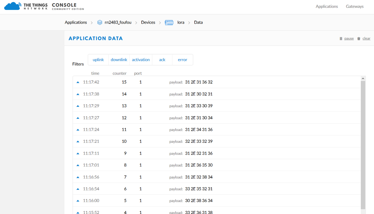
The payload contains the information encoded in hexadecimal, decoding it gives us the value coming from the the arduino.
We briefly tested the downlink and TX to RX functionalities with another group. The stability wasn't ideal, and we assumed it was because the LoRa chip was not listening all the time and couldn't consistently retrieve the data we sent to it. However, this feature wasn't essential for the project to we moved on.
## Designing a shield for our sensor on KiCad
During the TD and some labs, we created our own shield for the gas sensor. The aim was to create a shield that is adapted for the Arduino Uno but with our own components that we needed for the sensor.
We created a new project from a template for Arduino Uno. Firstly, we created different symbols that we needed and that are not already present in the librairies we have. We created the AOP LTC1050, the gas sensor and the LoRa module (RN2483). What is important is to have the good number of pins and to define what they correspond to.
In a second part, we created the different footprints we needed : the RN2483 and the gas sensor (we choose the TO-5-10 to keep the 10 pins of our sensor). What is important with the footprint is that it correponds exactly to the real object regarding the shape and size.
Then, we had to create the schematic of our shield, linking all the elements and the pins of every component. In that part, we choose to add three connectors. Two of them allow us to choose between the two sides of our sensor (because we implemented only one side in the AIME Labs). The third one is linked to the heater resistor, to connect it to the +5V or to the ground.
Another step consists in linking the symbols to the footprint to make the link between the components for the last part. In order to choose the good footprints for the others elements (connectors, resistor, capacitor), we went to see the ones available in GP and we measured them.

Finally, the last part consists in doing the routing. The idea is to link the different components with wires. It will define all the conexions that will be done on the final shield. As we have many components it is interesting to use "vias" (red lines on the image), otherwise it is not possible to route every component without crossing the wires. To place the components, we need to follow our schematic. For example, it is important to place C4 next to the AOP, and before R3 to respect the design we chose previously.

## Creating an interrupt-based circuit to send sensor data
The next step was to design the trigger system that would send data to TTN when the gas sensor output tension rises above a certain threshold. We could have gone for a simple solution involving polling in the main while loop, but that would be really on the processor and not really energy-efficient.
Instead, we went with a smarter approach using the interrupt capabilities of the Arduino Uno. The idea is to have a digital signal coming in on the ports 2 or 3 of the Uno, and activating the interrupt on the chosen port with a bit of code.
```cpp
pinMode(2, INPUT);
attachInterrupt(digitalPinToInterrupt(2),onGazTooHigh,CHANGE);
```
Doing this, we call the function onGasTooHigh everytime we have a change in the port D2 (in the function, we only send data if the change is a rising edge).
There is still one issue to address: the output signal of the sensor is analogical, ranging from 1V to 5V. In order to convert it to a digital signal going to a high level when rising above a threshold, we implemented a Schmitt Trigger.
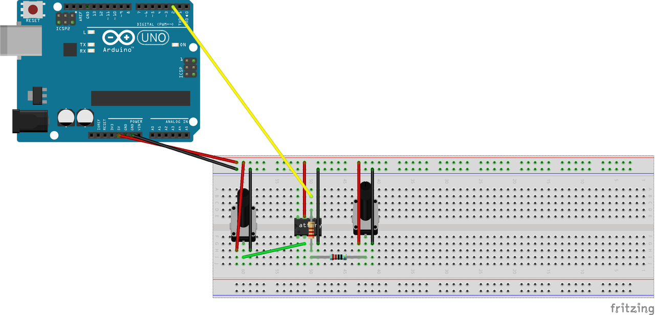
We implemented the trigger using a LTC1050 Operational Amplifier (you can find the datasheet [here](https://www.analog.com/en/products/ltc1050.html)). We used a potentiometer to set the reference tension for the threshold and to replace the sensor signal in the above model.
In the end our final hardware system, including the LoRa chip, looked like this:
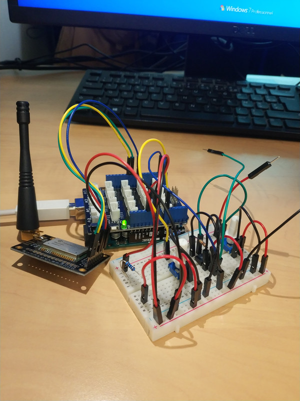
The schmitt trigger showed great results, especially in limiting oscillation of the tension around the threshold. It worked well with a potentiometer at first, then with the real gas sensor.
## Dealing with the system's energy consumption
Before trying to reduce the energy consumption of our system, we had to find a way of measuring it. First, we put a multimeter in ampere mode to look for a static value of the power consumption using the P = U * I relation.
Then, we took an oscilloscope to look for energy consumption when emitting in LoRa and listening to receive data.
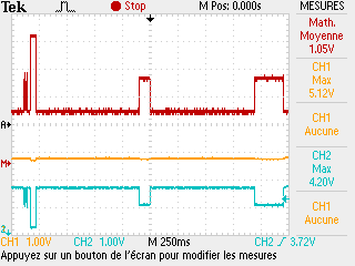
The first peak is the chip emitting data in LoRa, and the second and thirs peaks are the listening periods.
To reduce global energy consumption of the system, we chose to put the Arduino in sleep mode in the main loop, calling the putBoardToSleep function that looks like this:
```cpp
//Puts the arduino to sleep
//Returns when MCU gets awaken by interrupt
void putBoardSleep()
{
sleep_enable();
set_sleep_mode(SLEEP_MODE_PWR_DOWN);
// TODO check if other stuff are to be stopped
sleep_cpu();
}
```
## Using node-red to visualize uplink data and send downlink data
Node Red is a graphical tool based on Node.js used to connect devices, APIs and services from the web. In the context of the MOSH project, we used it to setup an uplink and downlink communication between our LoRa chip and TTN.
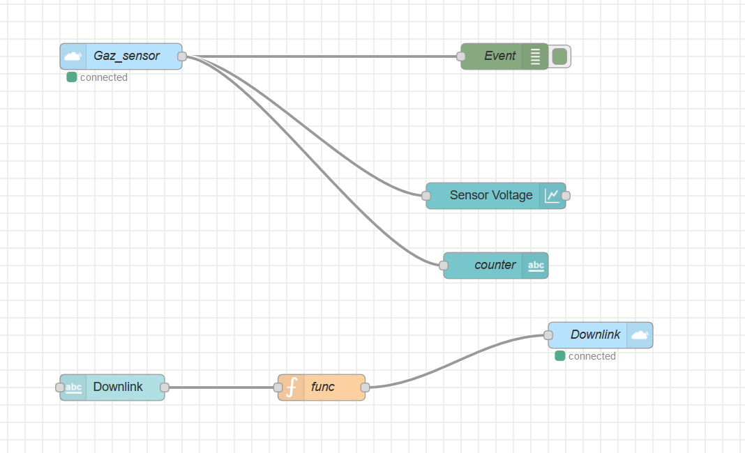
The flow we created accomplished two things :
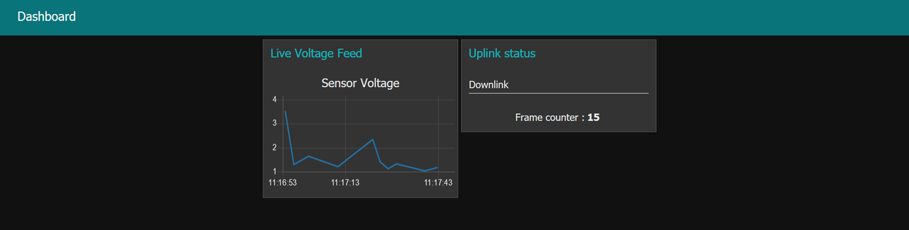
First, we connect directly to TTN, to obtain an display the data that is coming in from the board, and displaying it nicely in a dashboard, with a graph of tension value from a sensor over time.
Second, we created a downlink node that sent some raw data to the LoRa chip. The payload sent appeared on the TTN queue to be sent to the chip, even though we never seemed to manage to get it to actually be sent.
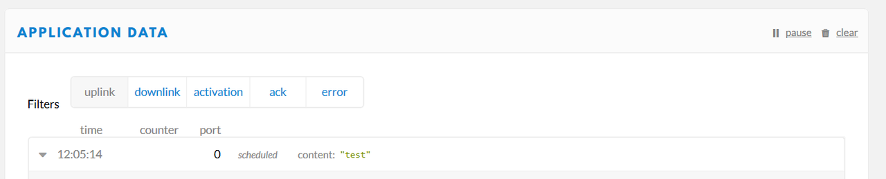
Here, we can see "uplink" in gray because we filtered the uplink messages, so only the downlink messages remain.
## Additional information
You can find the source code of our project on [our Github](https://github.com/VincentErb/ArduinoSensor)
This project was done in the context the 5ISS course, MOSH : Microcontroller and Open Source Hardware in 2019.
 Sign in with Wallet
Connect another wallet
Sign in with Wallet
Connect another wallet