---
tags: TI instaspin
---
# TI INSTASPIN FOC 使用心得
## 本實驗所使用馬達 硬體與開發環境基本參數如下
### 馬達
:pushpin: 碩陽BL90
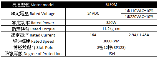
> from [碩陽電機](https://motiontech.tw.taiwantrade.com/product/%E7%84%A1%E5%88%B7%E9%A6%AC%E9%81%94-bl90m-%E8%A6%8F%E6%A0%BC-2059359.html)
instaspin motor electrical para ID result:
| Rs | Ld | Lq | flux |
| ------------ | -------------- | -------------- |:------------:|
| 0.0431745425 | 0.000113301474 | 0.000113301474 | 0.0494952388 |
:pushpin: 滑板車馬達
:pushpin: TACXNEO馬達
### 硬體
* 開發板 TI F28069M
附帶XDS100 v2電路 使用JTAG介面對TI F28069M燒錄

* 開發環境 Windows + CCSTUDIO + git bash
* Compiler TI C2000
* Debugger TI內建的燒錄器
* Motor drive/control HARDWARE
Drive board DRV8300DRGE-EVM
Extra board The 7th switch to control the energy flow.
[](https://www.ti.com/tool/DRV8300DRGE-EVM)
* DRIVE BOARD FROM EMTRC
待續
## SDK inverter客製化參數設定
### 頻率
//! \brief Defines the full scale frequency for IQ variable, Hz
//! \brief All frequencies are converted into (pu) based on the ratio to this value
//! \brief this value MUST be larger than the maximum speed that you are expecting from the motor
motor to be run to 10 KRPM with field weakening; Hz =(RPM * Poles) / 120
==需大於馬達最高電器頻率,否則會遺失更新命令。==
```
#define USER_IQ_FULL_SCALE_FREQ_Hz (120)// 800 Example with buffer for 8-pole 6 KRPM
```
### DCBUS電壓
//! \brief Defines full scale value for the IQ30 variable of Voltage inside the system
//! \brief All voltages are converted into (pu) based on the ratio to this value
//! \brief WARNING: this value MUST meet the following condition: USER_IQ_FULL_SCALE_VOLTAGE_V > 0.5 * USER_MOTOR_MAX_CURRENT * USER_MOTOR_Ls_d * USER_VOLTAGE_FILTER_POLE_rps,
//! \brief WARNING: otherwise the value can saturate and roll-over, causing an inaccurate value
//! \brief WARNING: this value is OFTEN greater than the maximum measured ADC value, especially with high Bemf motors operating at higher than rated speeds
//! \brief WARNING: if you know the value of your Bemf constant, and you know you are operating at a multiple speed due to field weakening, be sure to set this value higher than the expected Bemf voltage
//! \brief It is recommended to start with a value ~3x greater than the USER_ADC_FULL_SCALE_VOLTAGE_V and increase to 4-5x if scenarios where a Bemf calculation may exceed these limits
//! \brief This value is also used to calculate the minimum flux value: USER_IQ_FULL_SCALE_VOLTAGE_V/USER_EST_FREQ_Hz/0.7
==DC BUS電壓==
```
#define USER_IQ_FULL_SCALE_VOLTAGE_V (24.0) //
```
### ADC scale 電壓
//! \brief Defines the maximum voltage at the input to the AD converter
//! \brief The value that will be represented by the maximum ADC input (3.3V) and conversion (0FFFh)
//! \brief Hardware dependent, this should be based on the voltage sensing and scaling to the ADC input
==根據分壓電阻比例計算詳細計算方式可參考==

```
#define USER_ADC_FULL_SCALE_VOLTAGE_V (66.32) // 66.32 drv8301_revd voltage scaling
```
### 電流
//! \brief Defines the full scale current for the IQ variables, A
//! \brief All currents are converted into (pu) based on the ratio to this value
//! \brief WARNING: this value MUST be larger than the maximum current readings that you are expecting from the motor or the reading will roll over to 0, creating a control issue
==驅動版電流上限,或設置為馬達最大驅動電流==
```
#define USER_IQ_FULL_SCALE_CURRENT_A (41.25) // 41.25 Example for drv8301_revd typical usage
```
### ADC scale 電流
//! \brief Defines the maximum current at the AD converter
//! \brief The value that will be represented by the maximum ADC input (3.3V) and conversion (0FFFh)
//! \brief Hardware dependent, this should be based on the current sensing and scaling to the ADC input
==一般設置為兩倍的USER_IQ_FULL_SCALE_CURRENT_A,如此能用到完整的12bits ADC value range(0~4096)==
```
#define USER_ADC_FULL_SCALE_CURRENT_A (82.5) // 82.5 drv8301_revd current scaling
```
### scale factor
//! \brief Defines the voltage scale factor for the system
//! \brief Compile time calculation for scale factor (ratio) used throughout the system
//! \brief Defines the current scale factor for the system
//! \brief Compile time calculation for scale factor (ratio) used throughout the system
```
#define USER_VOLTAGE_SF ((float_t)((USER_ADC_FULL_SCALE_VOLTAGE_V)/(USER_IQ_FULL_SCALE_VOLTAGE_V)))
#define USER_CURRENT_SF ((float_t)((USER_ADC_FULL_SCALE_CURRENT_A)/(USER_IQ_FULL_SCALE_CURRENT_A)))
```
### 電壓感測濾波RC
//! \brief Defines the analog voltage filter pole location, Hz
//! \brief Must match the hardware filter for Vph
```
#define USER_VOLTAGE_FILTER_POLE_Hz (545.0608) // 335.648, value for drv8301_revd hardware
```

### R/L時間常數
//! \brief Defines the R/L estimation frequency, Hz
//! \brief User higher values for low inductance motors and lower values for higher inductance
//! \brief motors. The values can range from 100 to 300 Hz.
==此頻率需小於USER_IQ_FULL_SCALE_FREQ_Hz==
```
#define USER_R_OVER_L_EST_FREQ_Hz (120) // 300 Default
```
### 最大電壓向量
//! \brief Defines the maximum Voltage vector (Vs) magnitude allowed. This value sets the maximum magnitude for the output of the
//! \brief Id and Iq PI current controllers. The Id and Iq current controller outputs are Vd and Vq.
//! \brief The relationship between Vs, Vd, and Vq is: Vs = sqrt(Vd^2 + Vq^2). In this FOC controller, the
//! \brief Vd value is set equal to USER_MAX_VS_MAG*USER_VD_MAG_FACTOR. Vq = sqrt(USER_MAX_VS_MAG^2 - Vd^2).
//! \brief Set USER_MAX_VS_MAG = 0.5 for a pure sinewave with a peak at SQRT(3)/2 = 86.6% duty cycle. No current reconstruction is needed for this scenario.(SPWM)
//! \brief Set USER_MAX_VS_MAG = 1/SQRT(3) = 0.5774 for a pure sinewave with a peak at 100% duty cycle. Current reconstruction will be needed for this scenario .(SVPWM)
//! \brief Set USER_MAX_VS_MAG = 2/3 = 0.6666 to create a trapezoidal voltage waveform. Current reconstruction will be needed for this scenario .(Over modulation)
==根據PWM調變方法,設定最大電壓向量==
```
// Set to 0.5 if a current reconstruction technique is not used. Look at the module svgen_current in lab10a-x for more info.
#define USER_MAX_VS_MAG_PU (0.5)
```
### ADC offset
//! \brief ADC current offsets for A, B, and C phases
//! \brief One-time hardware dependent, though the calibration can be done at run-time as well
//! \brief After initial board calibration these values should be updated for your specific hardware so they are available after compile in the binary to be loaded to the controller
//! \brief ADC voltage offsets for A, B, and C phases
//! \brief One-time hardware dependent, though the calibration can be done at run-time as well
//! \brief After initial board calibration these values should be updated for your specific hardware so they are available after compile in the binary to be loaded to the controller
==:pushpin:參數如何換算成實際物理量可見[Current and voltage sensing](https://hackmd.io/1xOFJ4SkTAaJQk_9HzGtag)==
```
#define I_A_offset (0.9914957285)
#define I_B_offset (0.9796131253)
#define I_C_offset (0.9839500189)
#define V_A_offset (0.4967727661)
#define V_B_offset (0.4938468933)
#define V_C_offset (0.4937015176)
```
### Inverter para SUMMARY
:pushpin: 總結更改驅動版所需要調整之參數如下
```
#ifdef DRV8300DIPW_EVM
#define USER_IQ_FULL_SCALE_FREQ_Hz (100.0)
#define USER_IQ_FULL_SCALE_VOLTAGE_V (48.0)
#define USER_ADC_FULL_SCALE_VOLTAGE_V (110.3025)
#define USER_IQ_FULL_SCALE_CURRENT_A (55.0)
#define USER_ADC_FULL_SCALE_CURRENT_A (110.0)
#define I_A_offset (1.054858565)
#define I_B_offset (1.075172186)
#define I_C_offset (1.061470509)
#define V_A_offset (0.4903128743)
#define V_B_offset (0.4880359769)
#define V_C_offset (0.4874520898)
#define USER_MAX_VS_MAG_PU (0.5)
#define USER_VOLTAGE_FILTER_POLE_Hz (545.0608)
#endif
#ifdef drv8301kit_revD
#define USER_IQ_FULL_SCALE_FREQ_Hz (300)
#define USER_IQ_FULL_SCALE_VOLTAGE_V (48.0)
#define USER_ADC_FULL_SCALE_VOLTAGE_V (66.32)
#define USER_IQ_FULL_SCALE_CURRENT_A (41.25)
#define USER_ADC_FULL_SCALE_CURRENT_A (82.5)
#define I_A_offset (0.9827720523)
#define I_B_offset (0.9960394502)
#define I_C_offset (0.9872170091)
#define V_A_offset (0.4928019643)
#define V_B_offset (0.4920911193)
#define V_C_offset (0.4916644096)
#define USER_MAX_VS_MAG_PU (2.0/3.0)
#define USER_VOLTAGE_FILTER_POLE_Hz (335.648)
#endif
```
### 馬達參數
:pushpin: 馬達參數整理如下以TACXNEO為例
```
#elif (USER_MOTOR == TacxNeo)
#define USER_MOTOR_TYPE MOTOR_Type_Pm
#define USER_MOTOR_NUM_POLE_PAIRS (16)
#define USER_MOTOR_Rr (NULL)
#define USER_MOTOR_Rs (0.0534)//(0.135258242)
#define USER_MOTOR_Ls_d (0.0000512)//(0.000802517345)
#define USER_MOTOR_Ls_q (0.0000512)
#define USER_MOTOR_RATED_FLUX (0.237)
#define USER_MOTOR_MAGNETIZING_CURRENT (NULL)
#define USER_MOTOR_RES_EST_CURRENT (5.0)
#define USER_MOTOR_IND_EST_CURRENT (-5.0)
#define USER_MOTOR_MAX_CURRENT (20.0)//40MAX
#define USER_MOTOR_FLUX_EST_FREQ_Hz (40.0)
#define IPD_HFI_EXC_FREQ_HZ (500)//937.5 // excitation frequency, Hz
#define IPD_HFI_LP_SPD_FILT_HZ (35.0) // lowpass filter cutoff frequency, Hz
#define IPD_HFI_HP_IQ_FILT_HZ (100.0) // highpass filter cutoff frequency, Hz
#define IPD_HFI_KSPD (30.0) //?? // the speed gain value
#define IPD_HFI_EXC_MAG_COARSE_PU (0.1) // coarse IPD excitation magnitude, pu
#define IPD_HFI_EXC_MAG_FINE_PU (0.1) // fine IPD excitation magnitude, pu
#define IPD_HFI_EXC_TIME_COARSE_S (0.8) // coarse wait time, sec max 0.64
#define IPD_HFI_EXC_TIME_FINE_S (0.8) // fine wait time, sec max 0.4
#define AFSEL_FREQ_HIGH_PU (_IQ(0.0 / USER_IQ_FULL_SCALE_FREQ_Hz))
#define AFSEL_FREQ_LOW_PU (_IQ(0.0 / USER_IQ_FULL_SCALE_FREQ_Hz))
#define AFSEL_IQ_SLOPE_EST (_IQ((float)(1.0/0.1/USER_ISR_FREQ_Hz)))
#define AFSEL_IQ_SLOPE_HFI (_IQ((float)(1.0/1.0/USER_ISR_FREQ_Hz)))
#define AFSEL_IQ_SLOPE_THROTTLE_DWN (_IQ((float)(1.0/0.05/USER_ISR_FREQ_Hz)))
#define AFSEL_MAX_IQ_REF_EST (_IQ(0.4))
#define AFSEL_MAX_IQ_REF_HFI (_IQ(0.4))
#define USER_MOTOR_FREQ_LOW (6.7) // Hz - suggested to set to 10% of rated motor frequency
#define USER_MOTOR_FREQ_HIGH (66.7) // Hz - suggested to set to 100% of rated motor frequency
#define USER_MOTOR_FREQ_MAX (80.0) // Hz - suggested to set to 120% of rated motor frequency
#define USER_MOTOR_VOLT_MIN (7.2) // Volt - suggested to set to 15% of rated motor voltage
#define USER_MOTOR_VOLT_MAX (48.0) // Volt - suggested to set to 100% of rated motor voltage
```
## LAB1 硬體驗證
可先用LAB 01 01b 01c 對CPU and INVERTER setup 進行驗證
### 主程式架構簡介
:pushpin: software Architecture

> from TI Motorware-Hal-Tutorial PDF
TI instaspin的範例是屬於bare-metal的形式,沒有OS在上面運行,取而代之的是HAL層與CTRL層,instaspin透過CTRL層建構FOC驅動算法,當然使用者也能夠自行建立,而CTRL層則透過抽象層HAL去直接存取硬體(bitwise operation),CTRL層的實做需掌握FOC算法些許馬達設計知識,而HAL層的實做則需要對照TI手冊中的記憶體位置進行bitwise operation。
而一般計算機的作業系統中,除對底層硬體進行抽象化的動作,更負責整體計算機資源的控管和任務的排程。
> BSP VS HAL
BSP (board support package) consists of a set of drivers for predefined development board. HAL is an abstraction layer, as name says, and it serves as a layer between drivers and application, so application developer would not need to dig into hardware level and understand all the tiny details. Drivers are pieces of code that ideally know every tiny detail about the hardware they work with. So basically, application uses HAL, HAL checks what's supported with current board from BSP and BSP provides a limited set of drivers. Since HAL is an abstraction, it may have many checks and other processing to make it universal. So when you need performance, you bypass HAL and talk directly to drivers at the price, you need to know many details about hardware and your code will be mostly limited to certain modes.
In other words,the BSP is a component that fits in with the HAL to provide support for a specific board. For example if you have library functions for a SPI interface you don’t want the application developer to have to worry about the details of which pins on the MCU are being used for SPI, which could differ from one design to another if an MCU supports pin remapping. The BSP typically takes care of setting up low level configuration like clock trees, pin assignments, the core clock, etc.
### HAL(hardware Abstraction Layer)
1. HAL module is the only module that can interface with the hardware. In this context, hardwareincludes MCU peripherals, and board functionality
2. No peripheral configuration should be done at a user’s interface level, since this doesn’t allow portability of the code.
3. HAL functions which are time critical, should be inlined for faster execution
:dart: [static inline function](https://hackmd.io/3O3oe0aZTo2JxPM_zTEUJA#static-inline-function)
4. Use of macros must be avoided, and use of inline functions should be used instead
提供晶片底層功能的驅動Function能夠增加程式的可移植性,TI 28069M底層功能API包括
* ADC 16 channels 12bits each
* CLK Main frequency 90M Hz
* CPU
* FLASH
* PWM Pulse width modulation
* PWR
* GPIO Genernal purpolse IO
* OSC
* PIE
* PLL 除頻或倍頻
* TIMER three counter
* WDOG 看門口主要功能是檢測程式運行時有沒有異常的執行時間,有的話可以讓MCU自動重製
### CTRL(control Layer)
提供FOC所需的API其中包括
* FILTER
* OFFSET 設定電壓電流sensor offset
* CLARKE abc to /alpha/beta
* IPARK DQ to /alpha/beta
* PARK /alpha/beta to DQ
* PID current, speed, position controller
* SVGEN SVPWM Generator
* TRAJ Smooth command
運用CTRL所實現的FOC如下圖,基本的FOC運算都實現在ctrl.c中,而核心(FAST)的無感測驅動方法則已經編譯成機器碼,無法進行修改。

:pushpin: Trace code
在int main()中各項參數初始化,包含
1. HAL ➝ MCU底層設定()
2. 參數設置保護
4. USER ➝使用者參數設定(各項馬達與驅動器參數)
5. CTRL ➝控制器參數設定
interrupt void mainISR()為FOC運行的主要迴圈,其斷頻為ADC soc interupt,mainISR()內於每個周期會更新各項參數。
1. ADC(電壓電流)
2. SVPWM output
3. CONTROLLER
4. 更新轉子角度
5. sin/cos、clarke和park運算
6. ..
### CLOCK TREE
:pushpin:系統除頻如下
* F28069M main frequency 90MHz
* PWM切換頻率 45MHz


> from TI instaspin user.h
:pushpin: clock 運作


> from [TI motorware userguide](ti.com/lit/ug/spruhj1i/spruhj1i.pdf?ts=1674107545625&ref_url=https%253A%252F%252Fwww.google.com%252F)
### 1b Open loop control
可用來驗證驅動版是否正常運作,接上馬達三相線與驅動版DC電源,根據馬達規格給定相應DC電壓,按照手冊操作1b範例。馬達最高轉速3000 RPM、四極對馬達,換算電氣轉速為200 Hz。額定電壓為24V(Line2Line BEMF peak為24V)。根據上述可設定參數(Vmin、Vrate、fmin、frate)。
:dart:[motor V/F control](https://www.twblogs.net/a/5b8941fa2b71775d1ce0dc0e)

>from TI instaspin_labs
V/F control 簡介V/F控制可理解為開迴路的FOC控制,已知馬達的反電動勢與轉速的比值為反電動勢常數,也就是說為了提高馬達轉速,我們需要同步增加DCBUS電壓,用來抵抗馬達的反電動勢(實際上就是增加PWM duty cycle)。根據上述可知圖中的斜直線斜率就是反電動勢常數。實施馬達V/F控制,分別量測三相電流看是有欠相,若均為完整弦波,則確認驅動硬體完好。

PHASE CURRENT->補圖
另外熟悉DAC的運用以及CCS scope的使用。
:pushpin:TI手冊量測結果如下圖。


>from TI instaspin labs
:pushpin:實際量測結果
CH1 -> CURRENT ADC VALUE
CH2 -> SVPWM VALUE
CH2訊號為空間向量調變([SVPWM](https://www.switchcraft.org/learning/2017/3/15/space-vector-pwm-intro))的Value,俗稱屁股波。

量測實際驅動中馬達Line2Line訊號如下圖,在設定2000RPM情況下,4極對馬達電氣頻率為133Hz,與量測結果相符。量測訊號峰值約為24伏。

### 1c closed loop control
在v/f控制架構下增加電流closed迴路控制

:dart: 理論補充
---
## LAB2馬達電氣參數鑑別
:dart:[【期中報告】無感測器技術應用於自行車訓練平台之研究0812\_final.pdf](https://t36209481.p.clickup-attachments.com/t36209481/8231d8ce-8d75-4a35-8b77-6eedb981cbd4/%E3%80%90%E6%9C%9F%E4%B8%AD%E5%A0%B1%E5%91%8A%E3%80%91%E7%84%A1%E6%84%9F%E6%B8%AC%E5%99%A8%E6%8A%80%E8%A1%93%E6%87%89%E7%94%A8%E6%96%BC%E8%87%AA%E8%A1%8C%E8%BB%8A%E8%A8%93%E7%B7%B4%E5%B9%B3%E5%8F%B0%E4%B9%8B%E7%A0%94%E7%A9%B60812_final.pdf)
使用FAST estimator估測馬達參數(Vdc、頻寬Kp、flux、Ld、Lq、Rs),注意此範例需將電阻電感等參數設定為NULL才能正常運作如下圖,因為此範例要求你使用FAST estimator。

USER\_MOTOR\_RES\_EST\_CURRENT ➝ 系統鑑別啟動電流(10%~20%馬達最大電流)。
USER\_MOTOR\_IND\_EST\_CURRENT ➝ 系統鑑別啟動電流。
USER\_MOTOR\_RES\_EST\_CURRENT ➝ 系統鑑別啟動電流。
USER\_MOTOR\_FLUX\_EST\_FREQ\_Hz ➝ 系統鑑別啟動頻率。
2a. source code均位於MCU的ROM中,無法供使用者查看
2b. Source code除Fast estimator均放置user的RAM中,可供使用者查看
2c. For low inductance motor提高PWM頻率
2d. "sw/modules/iqmath/src/32b/IQmathLib.h"開啟浮點數運算 IQmathLib.h

TI這個專案 只支援IQ24

>[REFERENCE](https://e2e.ti.com/support/microcontrollers/c2000-microcontrollers-group/c2000/f/c2000-microcontrollers-forum/886571/ccs-tms320f28069m-instaspin-foc-how-to-change-iq24-to-iq20)
>:dart:[IQ_MATH介紹](https://hackmd.io/@TOMT/HkYB9OUso)
---
## LAB3 ADC offset calibration
3-a 更新user.h,輸入馬達電阻(Rs)、電感(Lsd, Lsq)和磁交鏈(Flux\_VpHz (Rated flux))等參數,跳過參數鑑別步驟,但須手動更新電壓與電流的ADC offsets。註﹔一般FOC驅動只需要偵測三相電流,以進行電流迴路的運算,但此TI的instaspin方案,因為是sensorless方案所以有增加三相電壓資訊(細節後續說明)
:dart:[電壓、電流回授物理量轉換與offset的物理量](https://app.clickup.com/36209481/docs/12h0u9-1660/12h0u9-6380)
You can Bypassing motor identification and loading motor parameters from user.h.
Storing the voltage and current offsets for future bypassing.
3-b 使用剛剛所設定的電壓電流offsets參數,跑起程式並確認adcBias的offset與user.h裡一樣。
3-c 使用浮點數運算
---
## LAB4 轉矩模式
Disable速度迴路僅使用電流迴路如下圖,也就是所謂的轉矩模式。當馬達在轉矩模式給定轉矩命令(iq電流命令),可想像成汽車或機車的油門,當馬達空載的情況下,馬達會一直加速,直到馬達反電動勢(BEMF=Ke\*We)達到所設定的DC BUS電壓,此時若沒有進行弱磁控制,馬達即達到最高轉速。
:pushpin:
iq電流命令為馬達的line2line電流peak值。
id電流命令可進行flux weaking控制

>from
## 4-a 使用浮點數運算
Q. 為甚麼PWM頻率量起來是90K? SVPWM兩個周期算一組 確認PWM頻率
Q. 若使用fpu32功能進行浮點數運算,是否還須使用Q函數?
---
## LAB-5 PID Speed and Current controller Tuning
電流迴路PID控制器設計,有關PID控制器相關知識,建議可以詳讀[古典控制理論](https://www.books.com.tw/products/0010829177)。
簡單來說針對各種不同的控制系統,我們會設計相對應的控制器,此控制器首先要保證系統的穩定性,使系統能夠收斂至所設定的reference命令如下圖,接著我們能夠透過調整PID參數調整系統的響應表現(settling time、over shoot、stable state error)。

>from wiki
以馬達控制系統來說,馬達系統為一階系統,我們一般透過Pole-Zero cancelation的技巧對其進行控制器設計如下圖

>from me
上述為連續控制系統的設計,一般來說當我們在s-domain設計完成的控制器,我們需要將其轉換成離散系統(z-domain),且對其進行離散補償的動作(EX﹔Pre-warping)。但在馬達系統中與電源轉換器相較之下,對於各項控制性能(settling time、over shoot、stable state error)較無嚴格要求,所以一般只簡單將控制器離散化,且通常以經驗法則去調製系統頻寬(參考TI Instaspin手冊)。
在設計電流迴路PID控制器時,一般可簡單以量測所得馬達電器參數(電阻電感)進行設計,但在設計速度PID控制器時,需要馬達物理參數慣量與阻尼,實務上難以準確量測,所以本實驗TI有提供相關速度PID控制器調製方式,但目前公司相關應用不太需要速度控制,故以下省略。
:dart:[TI SDK速度迴路PID控制器調製方法](https://app.clickup.com/42073237/docs/183z4n-3280/183z4n-21440):dart:[PID CONTROLLER](https://app.clickup.com/42073237/docs/183z4n-3280/183z4n-3420)
## LAB 9 field weakening(弱磁控制)
一般的FOC控制僅控制Iq命令,而Id命令則保持控制為0A,但當受控馬達不是SPM馬達,將Id控制在0A就不是最佳的控制條件。
而所謂的弱磁控制,就是控制Id!=0,而因為d軸的物理意義與馬達永久磁鐵磁通有關,所以當Id!=0會有增強或弱化磁鐵磁場的效果,故稱弱磁/強磁控制。
:dart: [MTPA CONTROL](https://www.slideshare.net/ssuser46ea1f1/mtpapptx)
## LAB 10
進階的應用包括過調變技術 無感測flying start 雙馬達控制
### 10-a over-modulation
SPWM & SVPWM
傳統的SPWM與SVPWM分別最高可達到的向量振幅分別為0.5與1/sqrt(3)

最高可的直流電壓使用率分別為86.326%與99.7%

:dart:詳細推導見講義[Chapter 4\_SVPWM.pdf](https://t36209481.p.clickup-attachments.com/t36209481/9dce1c67-1d61-4f23-8275-1c1e31972068/Chapter%204_SVPWM.pdf)
若對驅動器進行三次諧波插入則可將直流電壓使用率達到115%,詳細方式可見
:dart:[SVPWM Over Modulation](https://www.switchcraft.org/learning/2017/3/15/space-vector-pwm-intro)
在LAB10a中實際進行實驗結果為
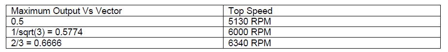
在相同的DC BUS電壓下,馬達可達到的最高轉速不同。
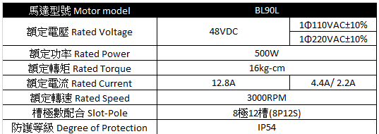
>from 碩陽BL90L
| Maximum Output Vs Vector | Top Speed |
| ---| --- |
| 0.5Vdc | 3690 RPM |
| 1/sqrt(3)Vdc | 4100 RPM |
| 2/3Vdc | 4500 RPM |
:dart:[TI SDK overmodulation實現方式簡介](https://app.clickup.com/42073237/docs/183z4n-3280/183z4n-21460)
---
### 10-e Flying start
偵測馬達初始轉速與轉子位置,在啟動時能減少馬達的頓挫感。
針對滑板車的應用,流程圖如下,會偵測馬達的最高轉速,並在馬達啟動時以速度LOOP追到該轉速,接著切換成轉矩模式,並提供使用者更新轉矩命令
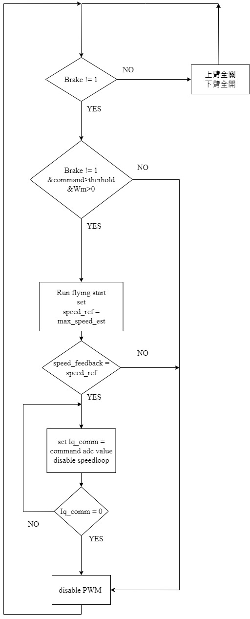
>from me 適用於滑板車
---
### 10-d dual motor control lab-10d
雙馬達的應用,須注意cpu的使用率和pin腳的設定
CPU usage

( timer\_delta\_avg \* (1/USER\_SYSTEM\_FREQ\_MHz) ) / ( 1 / USER\_ISR\_FREQ\_Hz )
(959\*(1/90MHz)) / (1/15kHz) = 0.159
---
## LAB5C Physic parameter ID
本實驗會有瞬間大電流的控制,進行5C實驗建議使用TI原廠驅動版,不然會有爆板風險。
Inertia(J)單位為A/kRPM
Friction(B)單位為A/kRPM
---
## LAB11
在本實驗中以sliding mode的無感測驅動,加入阻抗控制、DC電壓保護、UART和可變電阻等功能,初步實現訓練台功能。但此模式下在低速時效果不佳,與此無感測架構的原理有關。另外本實驗有別於前面的LAB,將整個FOC架構從CTRL全部搬到main.c中,使用者可先trace這個lab的code,較方便了解整體架構。:dart: [SLIDING MODE](https://app.clickup.com/42073237/v/dc/183z4n-3280/183z4n-3380)
## LAB20
相較於lab11與前面的lab,lab20已入新的程式架構,一樣整個FOC架構放到main.c中,但利用CTRL包住控制器的部分,方便使用者新增控制器或修改控制器輸出。


## LAB21 High Frequency Injection
:dart:[Sliding mode](https://hdl.handle.net/11296/6sktat):dart:[High frequency injection(HFI)](https://hdl.handle.net/11296/5m988y)
LAB21程式架構與lab20相同,但是此實驗引入**高頻注入法**,高頻注入法是一種馬達無感測驅動方式,相較於前述範例是使用FAST也就是滑動模式觀測器(Sliding mode observer)。而一般來說在使用observer的方式估測角度時,會受到反電動勢強弱的影響,所以當馬達轉速過低時observer難以估測角度;相較於Sliding mode,高頻注入法(HFI)是在d軸額外注入高頻訊號,不會因為馬達轉速而影響轉子角度的估測。
另外根據TI instaspin方案LAB21中的簡介,高頻注入加上FAST的混合無感測驅動模式,能夠有效增加馬達驅動的速度範圍。

>from TI instaspin

:pushpin:本實驗所使用馬達基本參數如下圖
| 馬達型號 | Tacxneo 2t |
|:------------------------------:|:----------:|
| 額定電壓 Rated Voltage | 100VDC |
| 額定功率 Rated Power | 2.2 kW |
| 額定轉矩 Rated Torque | 45Nm |
| 額定相電流 Rated Phase Current | 45.8A |
| 額定轉速 Rated Speed | 250 RPM |
:pushpin:電氣參數
| Rs | Ld | Lq | \lambda | Kt | Ke |
| ---- | ---- | ---- | ------- |:---:| --- |
| | Text | Text | | | |
根據TI instaspin參數調校步驟
STEP0 須先得知馬達電氣參數(Rs Ld Lq)
STEP1 選擇注入訊號頻率 Excitation Frequency (excFreq_Hz)
$$
ExcFreq = \frac{Rs}{Ld}\times10
$$
* The actual excitation frequency is determined by: ExcFreq
$$
ExcFreq = \frac{ISR}{2}\times\frac{1}{IntVal}
$$
* The ISR frequency = 15 kHz
STEP2
## Reference
[1]