# Learn OpenGL - Chapter 9 (Coordinate Systems)
###### tags: `opengl`
---
- A point can be mapped into different coordinate systems using matrix multiplications.
- Let's follow a box through the coordinate systems it has to go through to be displayed on your monitor.
- The box starts in the **local space**. It can be helpful to imagine that this is a space where only vertices of the box exist, and their coordinates are all relative to its **origin** (0, 0, 0).
- When we hard-coded a triangle's vertices like below:
```c=
float vertices[] = {
-0.5f, -0.5f, 0.0f,
0.5f, -0.5f, 0.0f,
0.0f, 0.5f, 0.0f
};
```
- We were specifying the vertices of the triangle by their local space coordinates. Try imagining where the origin would be visualized on the triangle.
- The box then needs to be placed in the **world space**, a coordinate system which describes how it exists in the "world" along with every other object. The box is **scaled**, then **rotated**, finally **translated** into the world space.
- The three transformations correspond to three different matrices, and the order of multiplication matters! See Ch. 8. Their product is what we call a **model matrix**.
- Then, for a **camera** observing this world, imagine how it perceives the world - It knows what is **in front, left, right, back, up, or down** of it. These directions form another coordinate system describing what the camera sees. Our box is then sent into this coordinate system, **view space**. The transformation used is represented by a **view matrix**.
- Every camera has its own view space, but for *rendering* to the screen, we usually only care about one particular camera's view space.
- Usually, the *basis* of the coordinate system is taken to be the **up**, **right**, and **front** vectors of the camera in world space. More in Ch. 10.
- From the camera's point of view, there are sections where it simply cannot see. We don't need to render what it cannot see, so we *clip* it, and only what the camera can see is left.
- You can imagine this process to be like how everything around you reflects light and projects how they look into your eyes. The back of your chair, for example, would not be able to reflect any light that can project onto your eyes, so it is "clipped" from your point of view.
- Note that this is a *projection* from a three-dimensional space to a two-dimensional space, represented by a **projection matrix**.
- Coordinates in the clip space are then mapped onto your viewport, into screen coordinates, which directly correspond to **fragments** which your fragment shader would process.
---
* Just like how you can switch out a camera's lens for different photographic effects, you can change how the camera perceives the view space by changing how it is *projected* into its clip space. In other words, changing its **projection matrix**, which describes a *frustrum* box where everything that falls out of it gets clipped.
* The **orthographic projection** is best described by how *every parallel line in the world space remains parallel after the projection*. It is often used in engineering.
* The frustrum of the orthographic projection is represented by two identically-sized planes, the near plane and the far plane, and the distance between them. Note that the planes are parallel to each other.
* Below is the function that generates the projection matrix of an orthographic projection.
```cpp=
// left: Where a plane's left edge is, on the camera's right axis.
// right: Where a plane's right edge is, on the camera's right axis.
// bottom: Where a plane's bottom edge is, on the camera's up axis.
// top: Where a plane's top edge is, on the camera's up axis.
// zNear, zFar: The distances of the planes from the camera.
glm::mat4 proj = glm::ortho(left, right, bottom, top, zNear, zFar);
```
* The **perspective projection** is more realistic than the orthographic projection, taking in account of the curved surface of an eye or a camera's lens. In short, parallel lines coincide at an infinitely-far point.
* This is achieved by changing the $w$ component of a vertex such that it increases as the vertex gets farther away from the camera. The $x$,$y$, and $z$ components of the vertex are divided by $w$ in a step called the *perspective division* to normalize the coordinates and achieve the effect of points seeming to converge to a single point infinitely far away.
* Mathematically, $\displaystyle\lim_{w\rightarrow \infty}(x/w,y/w,z/w) = (0,0,0)$
* Below is the function that generates the projection matrix of a perspective projection.
```cpp=
// fovy: Field of view, in radians. Use glm::radians for clarity.
// aspect: The aspect ratio of the viewport.
// zNear, zFar: same as orthographic projection.
glm::mat4 proj = glm::perspective(fovy, aspect, zNear, zFar);
```
The product of the transformation matrices $M$ (Model), $V$ (View), and $P$ (Projection), $P\times V\times M$ (in this order!), is called the Model-View-Projection matrix, which, when applied to a point, sends it all the way from local space to clip space. You should send the MVP matrix to your shader as a *uniform*. (As it remains constant throughout the entire frame, across every point the shader is going to process)
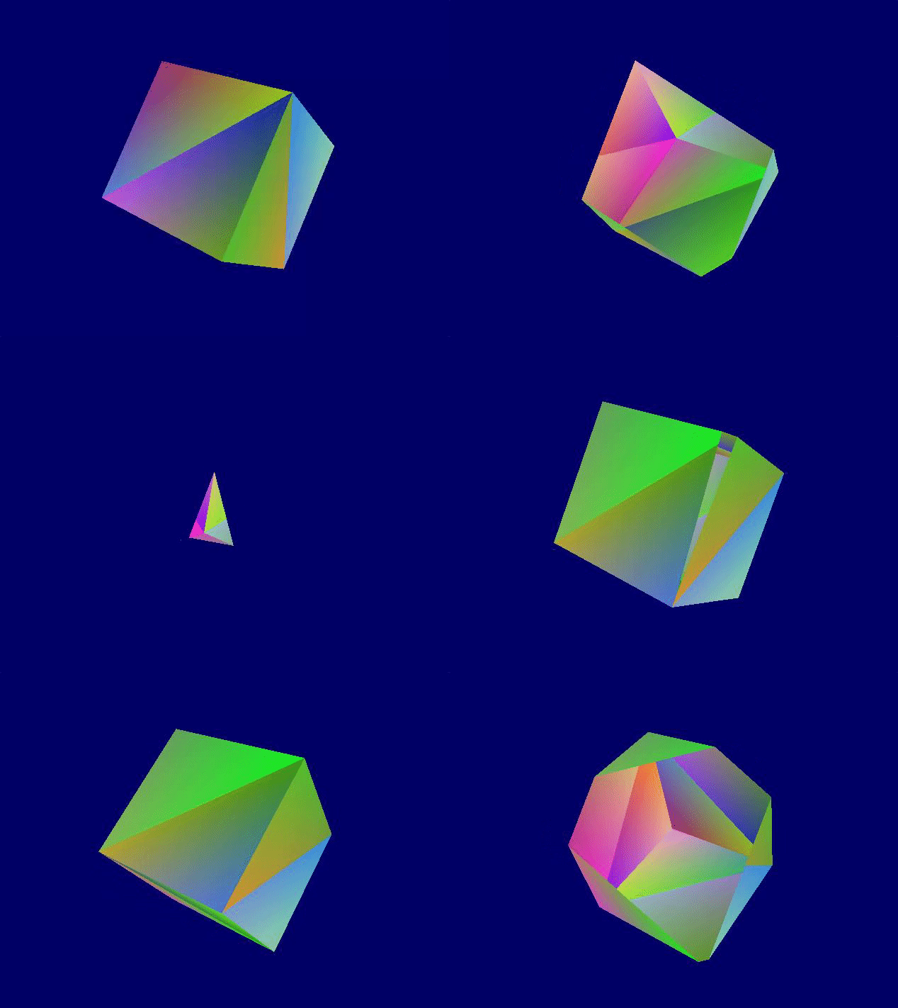
Demo: Perspective projection: Moving the near plane's distance back and forth.

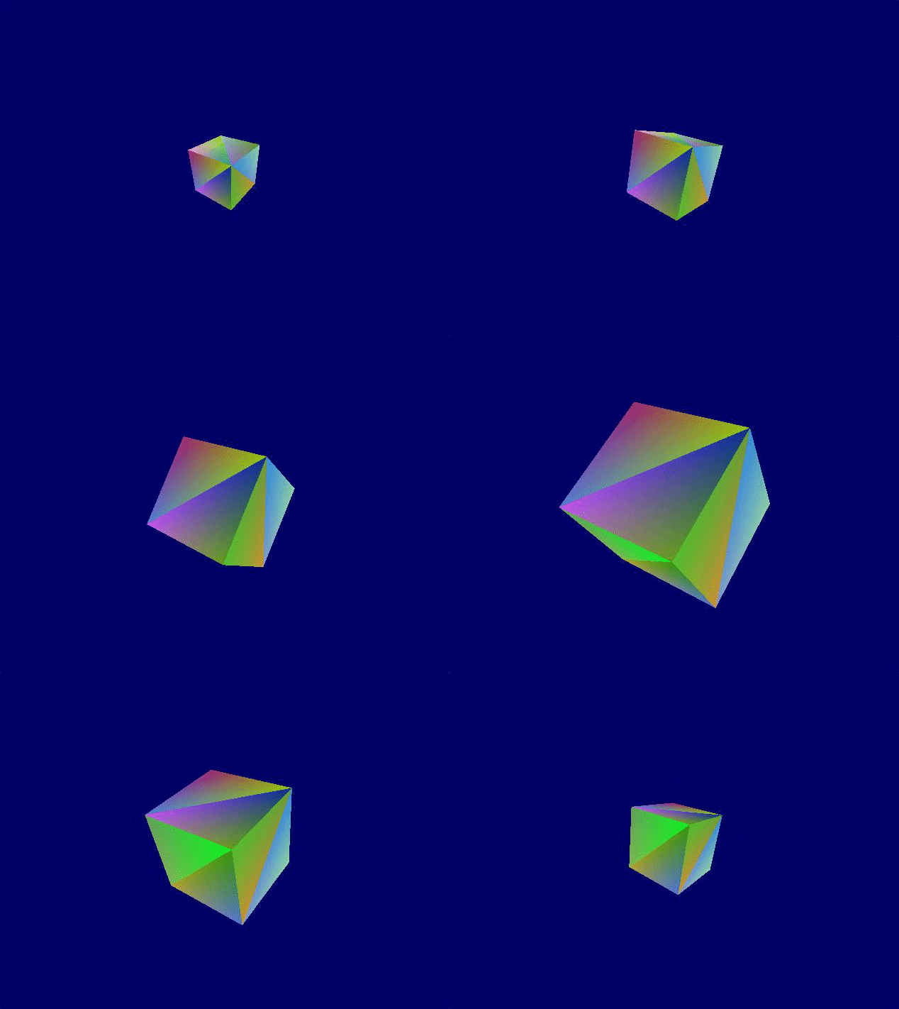
Demo: Perspective projection: Changing the field of view to oscillate between 45 degrees and 105 degrees.

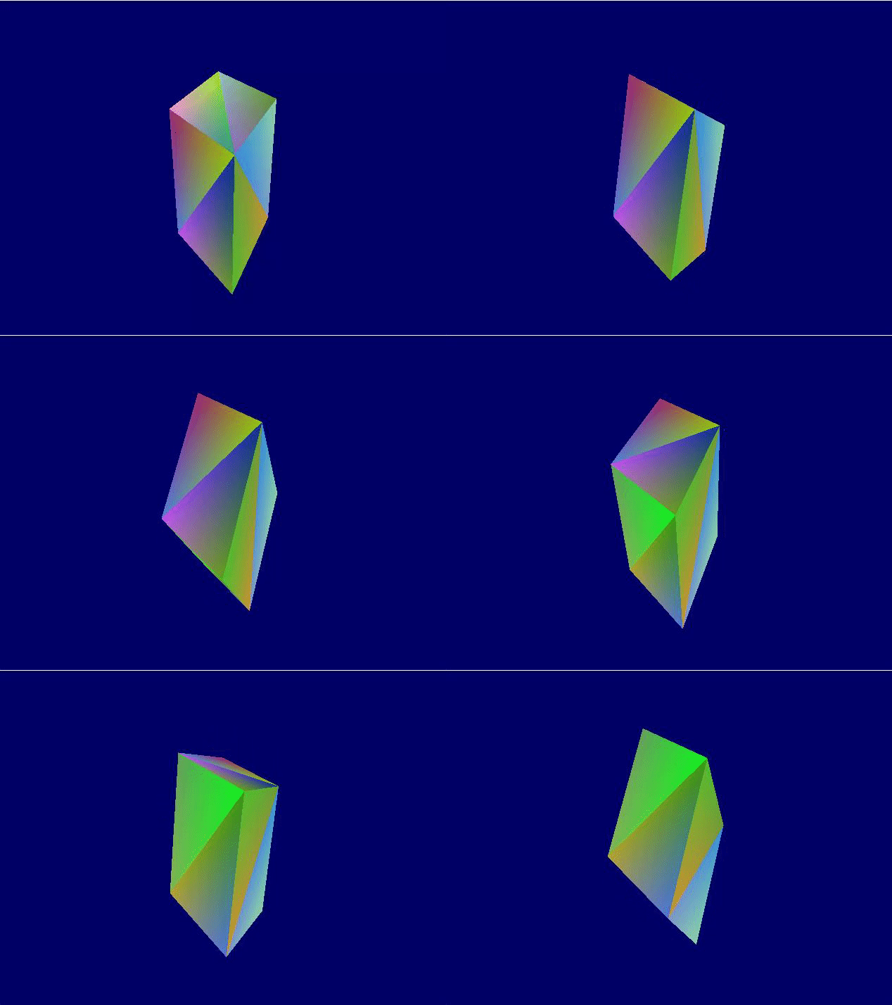
Demo: Perspective projection: Doubling the aspect ratio relative to the window's aspect ratio.
