# Basics of L293D Motor Driver IC.
### Description:
The L293D is a dual H-bridge motor driver IC that allows bidirectional control of two DC motors or one stepper motor. It amplifies low-current control signals from a microcontroller to drive higher-current loads. Each channel can supply up to 600mA continuous current and withstand peak currents of 1.2A.
The L293D includes internal ESD protection, output clamp diodes, and high noise immunity, making it suitable for robotics and automation applications
### Features:
> Supply Voltage Range: 4.5V – 36V
> Separate logic supply (VSS: 5V) and motor supply (VS: up to 36V)
> Output Current: 600mA per channel
> Peak Output Current: 1.2A
> Internal Clamp Diodes for inductive load protection
> High Noise Immunity
> Operating Temperature: 0°C to 70°C
> Built-in ESD Protection
> Dual H-Bridge for bidirectional motor control
> Can control 2 DC Motors / 1 Stepper Motor
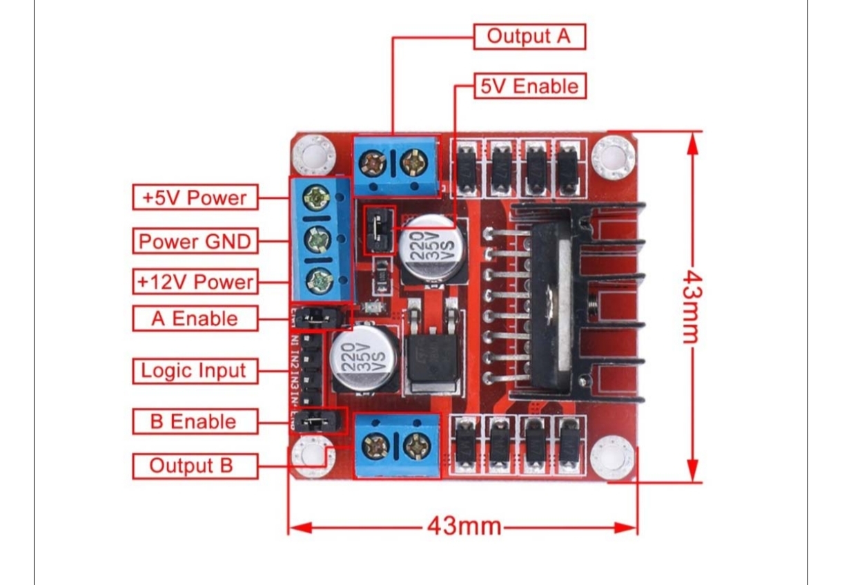
### Pin Configuration & Functions:
| Pin No. | Name | Function |
| ------- | -------- | ------------------------------------------- |
| 1 | Enable 1 | Enables left-side H-bridge (HIGH = active) |
| 2 | Input 1 | Logic input → controls Output 1 |
| 3 | Output 1 | Connects to motor terminal |
| 4, 5 | GND | Ground |
| 6 | Output 2 | Connects to motor terminal |
| 7 | Input 2 | Logic input → controls Output 2 |
| 8 | VS | Motor supply voltage (up to 36V) |
| 9 | Enable 2 | Enables right-side H-bridge (HIGH = active) |
| 10 | Input 3 | Logic input → controls Output 3 |
| 11 | Output 3 | Connects to motor terminal |
| 12, 13 | GND | Ground |
| 14 | Output 4 | Connects to motor terminal |
| 15 | Input 4 | Logic input → controls Output 4 |
| 16 | VSS | Logic supply voltage (5V) |
### Functional Block Diagram
>Two H-Bridges for motor control
>Enable pins (1, 9) act as master control switches
>Logic inputs control corresponding outputs
>Separate power supply for motors (VS) and logic (VSS)
### H-Bridge Switch Operation Table
| S1 | S2 | S3 | S4 | Operation |
| -- | -- | -- | -- | ------------------ |
| 1 | 0 | 0 | 1 | Motor moves right |
| 0 | 1 | 1 | 0 | Motor moves left |
| 0 | 0 | 0 | 0 | Motor free runs |
| 0 | 1 | 0 | 1 | Motor brakes |
| 1 | 0 | 1 | 0 | Motor brakes |
| 1 | 1 | 0 | 0 | Short Power Supply |
| 0 | 0 | 1 | 1 | Short Power Supply |
| 1 | 1 | 1 | 1 | Short Power Supply |
### Working Principle:
>The L293D acts as a current amplifier.
>Microcontroller outputs a low-current logic signal → IC amplifies it → drives DC motor.
>Motor direction is controlled by reversing polarity via H-bridge switching.
>Modes:
>>Forward / Reverse: Using (S1+S4) or (S2+S3)
>>Brake: Both inputs HIGH or mixed HIGH-LOW pattern
>>Free Run: All inputs LOW (motor coasts)