# **TASK 1: Introduction to Aerodynamics and Aircraft Structures**
**Objectives:** \
• Study Bernoulli’s Principle, Newton’s Third Law in aviation, and aerodynamic
forces. \
• Understand lift, drag, thrust, weight, and stability. \
• Learn about primary and secondary control surfaces.
**Outcomes and Learnings:** \
**Bernoulli's Principle:** It is a key concept in fluid dynamics, which states that as the speed of a fluid increases, the pressure within the fluid decreases. \
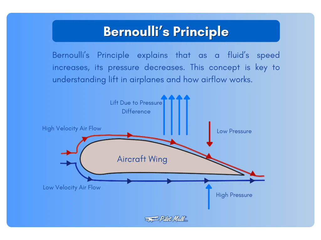
This principle is based on the conservation of energy, meaning the total energy of a fluid remains constant as it flows, and it applies to both liquids and gases. Essentially, a faster-moving fluid exerts less pressure, and a slower-moving fluid exerts more pressure.


**Newton's Third Law in Aviation:** When an airfoil, like a wing or a propeller, moves through the air, it forces the air downward (action). According to Newton's third law, there's an equal and opposite reaction that results in a lift, pushing the airfoil and the attached aircraft upward. \


In the case of **Helicopters**, when the main rotor of the helicopter rotates, it creates a torque in opposite direction on the body of the helicopter.
This is counteracted by the tail rotor, which is placed on the end of the helicopter.

There are other ways to counteract this torque, which is as follows:
1. **Use of Tandom Rotors**
The Indian Air Force operates **Boeing CH-47 Chinook**, which uses two rotors at either end of the fuselage.
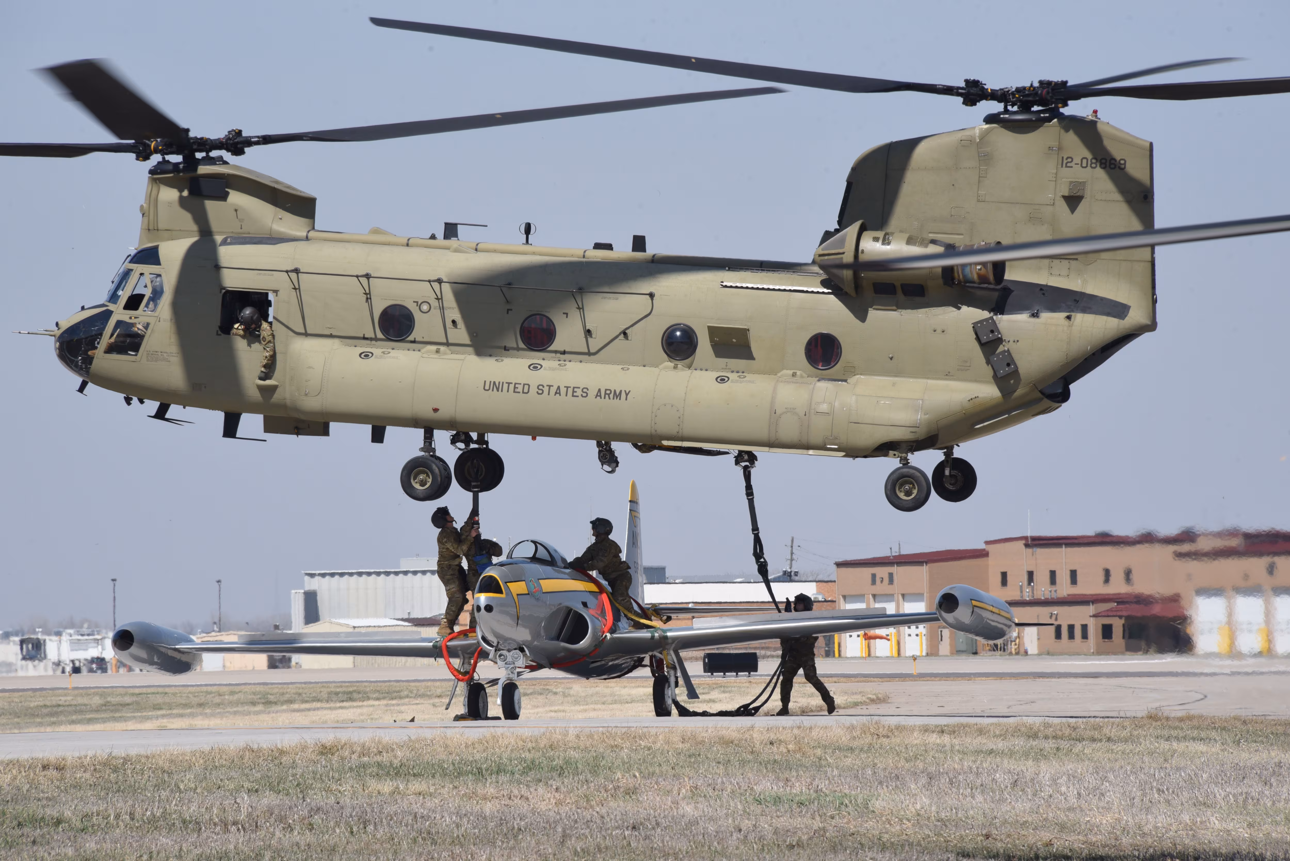
The rotors at one end of the fuselage would rotate in the opposite direction to that of the rotor at the other end of the fuselage.
This rotation of rotors in the opposite direction would cancel out the torque that is generated on the body of the helicopter.
This use of tandem rotors also offers extra maneuverability to the helicopter.

2. **Use of Proprotors**
The US Air Force operates **Bell Boing V-22 Osprey**, which uses rotors at either end of the wingspan.

The Osprey has two large proprotors, one on each wingtip.
These rotate in *opposite directions*:
+ One rotates clockwise, the other - counterclockwise.
+ The torque produced by one rotor is canceled by the torque of the other.
+ Net torque = 0, so the aircraft remains stable without needing a tail rotor.
V-22 Osprey can be used as a plane as well as a helicopter.
<iframe width="640" height="360" src="https://www.youtube.com/embed/j14p1hr-gBw" title="V-22 Osprey Transition" frameborder="0" allow="accelerometer; autoplay; clipboard-write; encrypted-media; gyroscope; picture-in-picture; web-share" referrerpolicy="strict-origin-when-cross-origin" allowfullscreen></iframe>
Source: Andre C. Youtube Channel
**Aerodynamic Forces:** The primary aerodynamic forces acting on an aircraft are lift, weight, thrust, and drag. These forces are fundamental to flight, balancing each other to enable an aircraft to stay aloft and move through the air. \

### **Factors Affecting Lift**
1. **Air Density**: Lift is directly proportional to air density.
+ More air density would mean the wings would be able to push more air downwards, hence generating more lift.
2. **Angle of Attack**: Lift increases with AoA — up to a point. Beyond the critical AoA, the wing stalls.
3. **Wing Area**: Larger wing area displaces more air, generating more lift. **Lift ∝ Wing Area**.
4. **Airspeed (Velocity)**: Faster airflow over the wing increases lift (as per Bernoulli’s principle). **Lift ∝ V^2**
5. **Environmental Conditions**: Wind direction, gusts, temperature, and humidity affect air density and flow around the wing.
**Stability:** In aircraft, stability refers to the tendency to return to a balanced state after being disturbed. \

**Factors Affecting Stability:** \
*Aircraft Design:* Wing shape, tail size, and wing placement all affect stability. \
*Weight Distribution:* The center of gravity plays a crucial role in stability. \
*Airflow:* The way air flows over the aircraft also influences stability. \

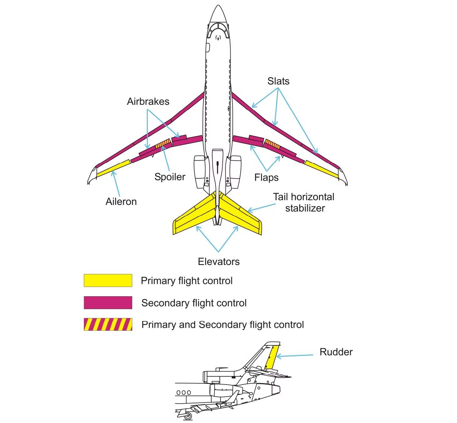
**Aircraft Control Surfaces:**
*Primary control surfaces* are essential for basic flight maneuvers, including ailerons (for roll), elevators (for pitch), and rudder (for yaw). \
*Secondary control surfaces* enhance performance and flight characteristics, including flaps, slats, spoilers, and trim tabs.
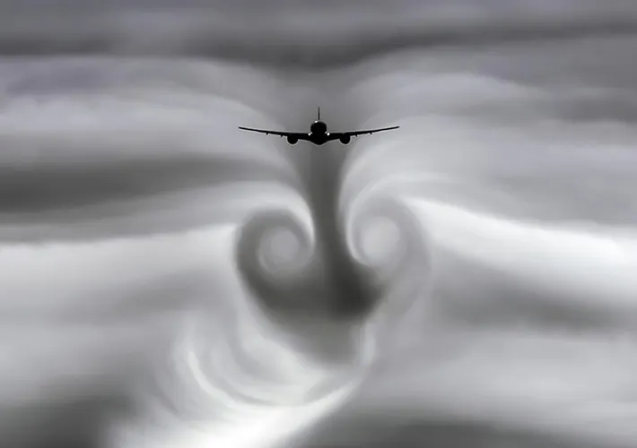
### **Turbulence in Planes**
*Turbulence* is the irregular or unsteady movement of air that causes an aircraft to bump, shake, or jolt during flight. It’s common and usually not dangerous, but it can feel unsettling.
It's caused by Jet stream (fast moving narrow air currents), storms, clouds which contain unstable air.
**How Planes Handle Turbulence**
- Aircraft are designed to withstand extreme turbulence.
- Pilots slow down to a safe "maneuvering speed" during turbulence.
- Pilots often change altitude to avoid turbulent layers.
**Propeller in a Turbulence**
Fewer blades on a propeller tend to be more efficient in terms of turbulence and overall performance.
A two-bladed propeller is often more efficient than a three-bladed one, and a three-bladed propeller is more efficient than a four-bladed one, especially in terms of minimizing turbulence.
# **Task 2: Design an Airfoil in Fusion 360**
**Objective:**
Design an airfoil with NACA 4412 coordinates in Fusion 360. Use the DAT to spline converter or canvas tool to sketch the airfoil. Understand terms such as angle of attack, camber line, chord line, and leading edge. Design two versions: one using a wood environment and another using composites. The wing should generate at least 5 newtons of lift at a wind speed of 25 m/s. \
**Learnings:** I learnt about NACA 4412 coordinates and basic terms related to planes.\
NACA stands for **National Advisory Committee for Aeronautics**. \
The four-digit NACA series follows a specific format: **NACA MPXX**\
**M = 4** → Maximum camber is 4% of the chord length.\
**P = 4** → Maximum camber location is at 40% (0.4c) of the chord from the leading edge.\
**XX = 12** → Maximum thickness is 12% of the chord length.

Basic Terms in Flying:
1.**Angle of Attack (AOA):** The AOA is the angle at which the chord of an aircraft's wing meets the relative wind. The chord is a straight line from the leading edge to the trailing edge.
2.**Leading Edge:** The part of the aircraft that meets the airflow (or fluid flow) first.
3.**Trailing Edge:** The part of an object where the airflow leaves.
4.**Chord Line:** It is an imaginary straight line that runs from the leading edge (front of the wing) to the trailing edge (back of the wing).
5.**Camber Line:** The camber line is an imaginary curved line that runs midway between the upper and lower surfaces of an airfoil.

# **TASK 3: Basic UAV Assembly & Components Familiarization**
**Objectives**: To understand and identify essential UAV components and their compatibility.
**Task:**
Identify and understand flight controllers (Pixhawk, APM), ESCs, motors, propellers, and battery management.
Learn about LiPo, Li-ion, and NiMH batteries, their charge cycles, and safety.
List all the components required to build a quadcopter with a minimum thrust-to-weight ratio of 3:1, each of the components should be compatible with each other.
Perform manual pen-and-paper calculations for flight time and thrust-to-weight ratio using component datasheets
Use E-Calc to verify the results.
**Outcomes and Learnings:**
**Flight Controller**
A *Flight Controller (FC)* is the central brain of a drone.
It is an electronic circuit board that processes input from sensors, receivers, GPS, and user commands — and then sends appropriate signals to the motors (via ESCs) to control the drone's flight.
The size of the drone sensors are very small.
For scaling these components, MEMS is used. MEMS stands for Micro-Electro-Mechanical Systems — a technology that integrates tiny mechanical structures (like sensors, actuators, or motors) with electronics on a micro-scale, typically on a silicon chip.
For more accurate and reliable data, *Sensor Fusion* technology is used. *Sensor Fusion* is a technology that combines data from multiple sensors to produce more accurate, reliable, and comprehensive information than what could be achieved using a single sensor alone.
**Pixhawk** is such open-source flight controller hardware platform widely used in drones, UAVs, and robotics. It supports advanced flight capabilities like autonomous missions, GPS-based navigation, and sensor fusion, and is typically used with ArduPilot or PX4 firmware.
**Nomenclauture of Motor**

**Nomenclature of Propeller**
*Propeller rating* is as : x*y which refers to as Diameter * Pitch in inches.
xyR means the propeller would rotate in reverse i.e. in Clockwise direction.
Some basic informations about propellers:

### Communication Protocols Used in Pixhawk:
1. **PWM** (Pulse Width Modulation)
*Used For:* Motor control via ESCs, RC input
*How It Works:* Varies signal width (in microseconds) to represent throttle/servo values.
*Limitations:* Susceptible to electrical noise; limited number of channels.
2. **MAVLink** (Micro Air Vehicle Link)
*Used For:* Communication between the flight controller and ground station (Mission Planner, QGroundControl), telemetry modules, companion computers (e.g., Raspberry Pi).
*Type:* Lightweight, bi-directional communication protocol
*Ports:* Typically over UART (serial), USB, or telemetry radios
*Purpose:* Telemetry, commands, sensor data, mission planning.
**MAVLink** is the universal language that connects your drone’s flight controller with the outside world — including the ground control station, telemetry radio, and even onboard computers.
### **Materials needed to assemble a drone**
1. **Battery:** More mAh → Longer flights, Heavy battery.
**C Rating** (or discharge rating) tells how fast a battery can safely deliver current without damaging itself. It’s especially important in LiPo batteries used in drones, RC vehicles, robotics, etc.
**Battery used:** LiPo 2500mAh - 30/45C
**LiPo battery** is used because of:
+ *High Power Output* (because of high C ratings)
+ *Lightweight* (it has best energy-to-weight ratios). LiPos are lighter than NiMH or Li-ion for the same power output.
+ LiPo cells can be made flat, thin, and compact, fitting tightly into drone frames.
+ LiPos can be charged quickly with proper chargers.
2. **Motor**
**Model:** T-Motor MN3110-780 (780KV)
+ Max. Efficiency Current is 4-10 A.
+ Suitable for Stable Flight.
+ Provides longer flight durations.
+ It uses Japanese bearings, which ensures smooth rotation, long lifespan and less vibrations.
+ This motor is ideal for Stable hovering, Cinematic footage, Low Noise Opertaion.
+ It's not meant for racing, but is perfect for endurance and camera drones.
3. **Propellers**
+ For the above selected motor, the ideal propeller dimensions would be 10 * 4.5 inches.
+ It’s a medium-size propeller that provides a good balance between thrust, efficiency, and motor load.
4. **ESC (ELectronic Speed Controller)**
+ The ESC regulates power from the battery to the motor based on control signals from the flight controller.
+ Selected Controller : max 20A
+ It handles full throttle peaks.
+ It stays within safe temperature limits.
+ Provides 20-25 % Efficiency
+ + *Recommended rule:*
ESC rating = 1.5 × expected max current
Max expected draw = ~15A
ESC should be at least 18.75–22.5A
Thus, 20A is just right, offering:
*Protection from overheating.*
*Tolerance for air density, wind, or aggressive flying.*
Formulae required for the calculations:

Thrust to Weight Ratio Calculations:


Flight time Calculations:

Result on the E-Calc Website:


# **TASK 4: Propeller Blade Design & Simulation**
**Objective:** To understand propeller fundamentals and simulate its aerodynamic performance.
**Outcomes and Learnings:**
### Basics of Propellers and their Nomenclature:
Every airplane propeller has the rating as: x*y, which refers to as Diameter * Pitch in inches.
*Example:* 10*4.5 means 10 inches is the Diameter and 4.5 inches is the Pitch.
*Diameter* is tip-to-tip size of the propeller.
*Pitch* is how far the propeller would travel forward in one revolution (in still air).

How the size of diameter and propeller affects the functions and applications of the propeller:


### Small Diameter + Higher Pitch (best for high speed drones)
Terminology
Small Diameter: Shorter span from tip to tip → spins faster, less drag, lower thrust.
High Pitch: Steeper blade angle → more air moved per rotation, higher speed.
### Larger Diameter + Lower pitch (best for heavy lift drones)
Terminology
Large Diameter: Bigger blade span → moves more air, generates more thrust, good for lift.
Low Pitch: Shallower blade angle → less forward movement per rotation, better for control.
### Clockwise(CW) and Counter-Clockwise(CCW) Propellers
**Need:** If all Propellers spin the same way, then the drone will spin uncontrollably in the opposite direction due to torque.
It cannot yaw or stabilize properly.
The flight controller cannot compensate for the unbalanced forces.
**Main Reason:** When a propeller spins, it creates torque (rotational force).
According to Newton’s Third Law, if all props spun the same direction, the drone’s body would spin in the opposite direction of the props — uncontrollably.
To cancel this, drones use equal numbers of CW and CCW props.
This opposite rotation pattern balances the torque and allows the drone to:
+ Stay stable in place
+ Yaw (rotate) when needed by adjusting motor speeds.
The other way to identify the clockwise and counterclockwise rotation is to check by rotating the propeller such that the leading edge faces the air first.
If the leading edge faces air first when rotating clockwise, then it's a clockwise rotating propeller. The naming of such a propeller would be like 6030R.
On the other hand, if the leading edge faces air first when its rotated counter clockwise, then it's a counter clockwise propeller. The naming of such a propeller would be like 6030.
Note: CCW is the normal rotation.
Example: 6030R means the propeller would rotate in reverse, i.e. Clockwise direction.
### Factors affecting Propeller Efficiency
### Key Factors Affecting Propeller Efficiency
| **Factor** | **Explanation** |
|----------------------------|----------------------------------------------------------------------------------|
| **1. Propeller Diameter** | Larger diameter props can move more air and generate more thrust at lower RPMs, improving efficiency—but they require more space. |
| **2. Pitch** | Higher pitch moves more air per rotation (good for speed), but may overload the motor. Lower pitch is better for low-speed control. Efficiency depends on matching pitch to the flight requirement. |
| **3. Number of Blades** | More blades = more thrust, but also more drag. Fewer blades = higher efficiency (less drag), but reduced thrust. |
| **4. Blade Shape and Airfoil** | Efficient blade designs reduce drag and improve lift. Thin, smooth, and well-tapered blades are generally more efficient. |
| **5. RPM (Rotations Per Minute)** | Efficiency is better at lower RPMs with larger props. High RPM increases drag and losses. Optimal RPM varies with design. |
| **6. Motor Matching** | An efficient prop must be matched with the right motor KV rating and power curve. A mismatch leads to poor efficiency and overheating. |
| **7. Material and Weight** | Lighter materials (like carbon fiber) reduce inertial load and increase responsiveness and efficiency. Heavier props may reduce efficiency. |
| **8. Air Density** | Higher altitude or hot weather = lower air density → reduced thrust and efficiency. |
| **9. Load (Thrust Requirement)** | A propeller running near its optimal load is more efficient. Overloading or underloading reduces efficiency. |
| **10. Cleanliness and Damage** | Dirt, nicks, or warping on the blades can cause turbulence and reduce efficiency. |
| **11. Installation Direction** | Incorrect orientation (e.g., CW vs CCW mismatch) results in poor performance or failure to generate thrust. |
| **12. Vibration and Balance** | Imbalanced props create vibrations, reduce efficiency, and stress the motor and airframe. |
### Designing Propeller in Fusion 360
The first step is to Open New Design and start the model making as guided in the referenced video.
Make the three profile planes and use Loft option to complete 3D sketch.
Duplicate the one side propeller on the opposite side of the cylinder.
Finish the sketch by doing some minor changes and the propller design is ready.

**Features Used in Fusion 360:**
**Sketch Tool:** For creating 2D profiles.
**Loft Tool:** For transforming 2D sketches into 3D geometries.
**Circular Pattern Tool:** For making the cylindrical part at one end of the propeller, after which the other side of the propeller is duplicated.
**Fit Point Spline** is a type of spline curve that passes through specific points (called fit points) you define in a sketch.
<iframe width="638" height="335" src="https://www.youtube.com/embed/E_nsXRWXXdI" title="Design Propeller in Fusion 360 I MARVEL UVCE" frameborder="0" allow="accelerometer; autoplay; clipboard-write; encrypted-media; gyroscope; picture-in-picture; web-share" referrerpolicy="strict-origin-when-cross-origin" allowfullscreen></iframe>
# **TASK 5: Understand about ESC**
**Objective:** To control the speed of a BLDC motor using Arduino UNO, ESC, and a potentiometer.\
**Outcomes and Learnings:** A BLDC motor stands for **Brushless Direct Current** Motor. It’s a type of electric motor widely used in drones, RC vehicles, robotics, and other electronics due to its efficiency, reliability, and performance.

**Arming of ESC**:
When initially powering the motor, the signal value must be the same or lower than the minimum value of 1 millisecond. This is called **arming of the ESC**, and the motor makes a confirmation beeps so that we know that it’s properly armed. \
In case we have higher value when powering, which means we have a throttle up, the ESC won’t start the motor until we throttle down to the correct minimum value. This is very convenient in terms of safety, because the motor won’t start in case we have a throttle up when powering.\
Every ESC has its own high and low points, and they might slightly vary. For example, the low point might be 1.2 milliseconds and the high point might be 1.9 milliseconds. In such a case, our throttle won’t do anything in the first 20% until it reaches that low point value of 1.2 milliseconds. To solve this issue, we can calibrate the ESC or set the high and low points as we want.
### **Functions of ESC**
1. **Throttle Control**: Converts input signals (from receiver or flight controller) into motor speed by adjusting voltage and current.
2. **Brushless Motor Commutation**: For brushless motors, it electronically switches the current through motor windings to create rotation.
An ESC needs calibration when it does not correctly interpret the full throttle range from your transmitter or flight controller.
**ESC Calibration**:
1. Begin with Throttle at Maximum (High Point)
Before powering the ESC, set the throttle input (via potentiometer or transmitter stick) to its highest position.
This signals the ESC: "This is the maximum throttle level."
Now, apply power to the ESC (connect the battery).
You’ll hear a series of beeps from the motor, indicating that the ESC has recognized the maximum throttle position.
2. Move Throttle to Minimum (Low Point)
After the beeps, wait about 2 seconds.
Reduce the throttle to its lowest position (idle or stop).
The ESC will register this as the minimum throttle level.
A final series of confirmation beeps will indicate
that calibration is complete.
3. The ESC is now calibrated.
<iframe width="674" height="379" src="https://www.youtube.com/embed/iA60GZ2lfl0?list=PLN5iTpKS9zTnxFYZch9ipEpEiBg9poPkI" title="Task: Speed control of DC motor -2 | MARVEL" frameborder="0" allow="accelerometer; autoplay; clipboard-write; encrypted-media; gyroscope; picture-in-picture; web-share" referrerpolicy="strict-origin-when-cross-origin" allowfullscreen></iframe>
<iframe width="674" height="379" src="https://www.youtube.com/embed/ID6iv4p6HUg?list=PLN5iTpKS9zTnxFYZch9ipEpEiBg9poPkI" title="Task : Speed control of DC Motor -3 | MARVEL" frameborder="0" allow="accelerometer; autoplay; clipboard-write; encrypted-media; gyroscope; picture-in-picture; web-share" referrerpolicy="strict-origin-when-cross-origin" allowfullscreen></iframe>
# **TASK 6: RF Communication in UAVs**
**Objective:** Learn about radio frequencies used in UAVs (2.4GHz, 5.8GHz, LoRa).
Understand the various security implications in the different wireless protocols used in drones, along with the emerging threats and ways of mitigation.
Understand the procedure which goes behind the binding of an ELRS receiver.
Bind the 2.4 GHz RP1 Rx with the TX 16S MK-ll.\
**Outcomes and Learnings:**
- A *frequency band* is a range of frequencies within the electromagnetic spectrum allocated for a specific purpose.
- Most commonly, there are two types of frequency bands that are widely used around the globe, i.e. 2.4 GHz and 5GHz.
- 2.4 GHz is the most commonly used frequency band which is used in other appliances too, such as oven and cell phones, which results in the interference with the the WiFi signal and slows down the speed.
- As a result, 5GHz was introduced, which is used by comparatively less devices, resulting in better WiFi signal.
- **Wireless Channel**: It is a way to fine tune and alter a frequency. (It can be imagined as an old radio on which the frequency needs to be changed so as to get the better signal for clear voice.)\
Higher number of non-overlapping channels would mean lesser interference, stable connections.
+ 2.4 GHz has 11 wireless channels.
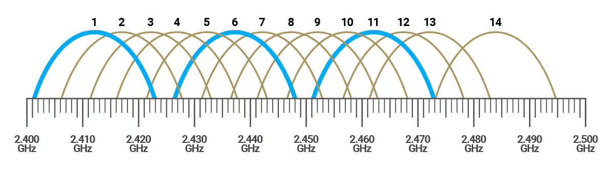
+ It has only 3 non-overlapping channels, namely Channel 1,6 and 11.
+ On the other hand, 5GHz has 25 non-overlapping channels.
---
| Feature | 2.4 GHz | 5 GHz |
|-------------------------------|-----------------------------------------------|-----------------------------------------------|
| **Frequency Range** | ~2.4 to 2.5 GHz | ~5.15 to 5.825 GHz (varies by region) |
| **Speed** | Lower maximum speed (up to ~600 Mbps) | Higher maximum speed (up to several Gbps) |
| **Range** | Longer range (better wall penetration) | Shorter range (weaker penetration) |
| **Channels Available** | 11 (3 non-overlapping) | 25 non-overlapping |
| **Interference** | Higher (used by many devices: Bluetooth, etc) | Lower (less congested, more channels) |
| **Best For** | Larger coverage areas with fewer devices | High-speed, short-distance connections |
| **Latency** | Typically higher | Lower latency (better for gaming, streaming) |
| **Device Compatibility** | Supported by almost all Wi-Fi devices | Newer devices required for full support |
---
**LoRaWAN**: Long Range Wide Area Network\
It uses unlicensed frequency band for long-range communication. It is built on top of LoRa (Long Range), which is a physical layer modulation technique.
It is classified into 3 classes: Class A, Class B, Class C.
| Class A | Class B | Class C |
|--------------------------------|-----------------------------------------------|-----------------------------|
| Longest battery life | Average battery life | Longest battery life |
| Stays in sleep mode for majority of the time | Listens to network perodically | Listens to network continuously|
| Example-Fire Alarm | Example- Metering of temperature, humidity | Example- Traffic monitoring |
**LoRa Architecture:** 
1. *Gateways:* It receives messages from the devices.\
Demodulates LoRa message (packet).\
Forwards packets to network server with the use of Internet or LAN.
2. *Network Server:* It handles authentication and authorisation.\
It schedules downlink messages.\
It communicates with application server.
3. *Application Server:* It receives messages from netwrok server and decrypts the data.
The frequency band used by LoRa varies region by region. In India, it operates in the 865–867 MHz band.
---
**Drone Components**:
| Component | Function | Key Protocols Used | Potential Vulnerabilities |
|------------------------|--------------------------------------------------------|------------------------------------------------------------------|------------------------------------------------------------|
| Command & Control (C2) | Transmits pilot instructions to the drone | 2.4 GHz/5.8 GHz Wi-Fi, FHSS, DSSS, LTE, SATCOM | Signal interception, jamming, protocol spoofing |
| Telemetry Data | Provides real-time flight data (position, altitude, speed) | MAVLink, DJI Lightbridge, LoRa, DroneCAN | Data injection, signal hijacking |
| Video Transmission | Sends live feed to the pilot or external system | FPV (Analog or Digital), OcuSync, Wi-Fi, 5G LTE | Man-in-the-middle (MITM) attacks, feed interception |
| Navigation & GPS | Enables autonomous navigation and geofencing | GPS, GLONASS, BeiDou, Galileo | GNSS spoofing, jamming, denial of service |
| Payload Data Link | Transfers sensor and payload data | 4G/5G, SATCOM, proprietary links | Data exfiltration, interference, encryption bypass |
---
### **Key Wireless Protocols & Security Risks in UAVs:**
i) 2.4 GHz & 5.8 GHz Radio Control (RC) Signals
- Widely used for drone control.
- Security Risks: Vulnerable to signal interception, hijacking, and jamming attacks
ii) Wi-Fi-Based Drone Control
- Drones equipped with Wi-Fi control are convenient to use.
- Security Risks: Man-in-the-middle (MITM) attacks,
Deauthentication attacks (Wi-Fi jamming),
Packet injection for remote takeover.
iii) MAVLink Protocol: Open-Source Telemetry Standard
- Used extensively in autonomous UAVs
- Security Risks: Unencrypted data exchange (default settings)\
Susceptible to data injection attacks, allowing unauthorized control.
iv) 4G/5G LTE & SATCOM-Controlled Drones
- Long range accessibility for drones over mobile networks.
- Security Risks:\
Harder to detect due to lack of RF emissions\
Cloud-based control allows remote operation from anywhere
### **Emerging Threats in Drone Communication Systems**
1.**GNSS Spoofing & GPS Jamming**\
Attackers can transmit counterfeit GPS signals, tricking drones into miscalculating their location.\
*Impact:* UAVs can be forced to change flight paths or even crash.\
*Countermeasure:* Multi-constellation GNSS receivers and inertial navigation backups.
2.**Signal Hijacking & Remote Takeover Attacks**\
Weak encryption allows attackers to inject false commands into drone control links.\
*Countermeasure:* Strong encryption (e.g., AES-256) and authentication-based command inputs.\
3.**Network-Based Attacks on Wi-Fi-Controlled Drones**\
Wi-Fi-controlled drones are highly susceptible to deauthentication and MITM attacks.\
*Countermeasure:* WPA3 encryption, SSID broadcasting disablement, and dynamic IP allocation.
### **Strategies for Securing Drone Communication Networks**
1.**RF Spectrum Monitoring**
Passive RF monitoring detects UAV emissions within the 300 MHz – 6 GHz range.\
Helps identify C2 links, telemetry beacons, and FPV signals in real time.
2.**Encrypted Telemetry & Secure Authentication**
Implementing secure command authentication prevents unauthorized access.\
End-to-end encryption minimizes hijacking risks.
3.**Deep Packet Inspection for Networked UAVs**
Cellular-connected drones can be identified via traffic analysis.\
Detects suspicious drone activity over LTE networks.
4.**Adaptive Counter-UAS Technologies**
AI-driven RF anomaly detection classifies drone activity.\
Multi-sensor fusion (RF, radar, EO/IR cameras) enhances detection accuracy.
---
### **ELRS**
- **Express Long Range System** is an open-source radio control protocol. It offers a number of features that make it an appealing option for use on FPV drones.
- ExpressLRS (ELRS) is one of several control link protocols used in drones to communicate between the transmitter (TX) and the receiver (RX).
- It's designed to provide low latency, long range, and high stability with its LoRa technology.
- The low latency and high performance of ELRS make it a popular choice for FPV (First Person View) racing and drone applications, where responsiveness and speed are crucial.
- Some of the advantages offered by ELRS are Low Latency, Long Range, Open Source, available in both frequency bands : 2.4 GHz (offers lower latency) and 900 MHz (better penetration).\
**Working**: ELRS is present in the hand controller and the ELRS receiver is present in the drone/quadcopter. It links with the hand controller and provides the wireless link which controls the drone.\
**Setup**:
- Install ExpressLRS Configurator (from GitHub)
- Flash Firmware to TX and RX
- Use same binding phrase in firmware.
- Bind Devices
- Auto-bind via binding phrase (recommended), or press physical bind button.
- Configure Betaflight
- Set UART for serial RX
- Set Receiver to CRSF protocol
- Check Channels & Failsafe
Some other **Drone Protocols** are:
| **Protocol** | **Full Form** | **Key Features** |
| ------------- | ------------------------- | ----------------------------------------------------------------------- |
| **CRSF** | Crossfire (by TBS) | Low latency, long range (900 MHz), supports telemetry |
| **SBUS** | Serial Bus (by FrSky) | Digital protocol, supports 16 channels, older but widely used |
| **IBUS** | FlySky iBUS | Digital, less noisy than PWM, used in FlySky systems |
| **PWM** | Pulse Width Modulation | Analog, one wire per channel, simple but outdated |
| **PPM** | Pulse Position Modulation | Combines multiple PWM signals into one wire |
| **FPort** | FrSky FPort | Combines SBUS + telemetry on a single wire |
| **Ghost** | ImmersionRC Ghost | Low latency, used for racing drones (2.4 GHz) |
| **Tracer** | TBS Tracer | High-speed 2.4 GHz protocol optimized for racers |
| **DSM2/DSMX** | Spektrum protocols | Used in Spektrum RC systems, DSMX offers better interference resistance |
# **TASK 7: Basics of PID**
**Objective**: Understand PID tuning for UAV stability\
Learn how GPS Hold and Altitude Hold work, tabulate the differences between the two\
Tabulate the differences between GPS Hold and Altitude Hold\
**Outcomes and Learnings**: In drones, a PID (Proportional-Integral-Derivative) control system is a sophisticated method for maintaining stable flight and precise control over various aspects like altitude, orientation, and movement. It works by continuously calculating the difference between the drone's desired state and its current state, then adjusting motor speeds to minimize that difference. \
P – Proportional
+ Reacts to the current error
The bigger the error, the bigger the correction.
I – Integral
+ Reacts to the accumulated past error
Helps eliminate long-term steady-state error.
D – Derivative
+ Reacts to the rate of change of error
Predicts future error, helps with stability and response speed\
An example to better understand it:\
Imagine driving a car to stay in the center of a lane:
+ P pushes you back toward the center the more you're off.
+ I remembers if you're consistently off to one side and corrects it.
+ D slows your steering response if you're overcorrecting too fast.
The final PID output is **added** to the current control input to adjust the system toward the setpoint.
---
**Altitude Hold** is used when flying in calm indoor/outdoor areas and want help with vertical stability.\
**GPS Hold** is used when you want the drone to hover in one place without drifting, especially outdoors.\
``GPS-Global Positioning System``\
The following tabular column provides more insight on the difference between the two.
| Feature | **Altitude Hold** | **GPS Hold** (Position Hold) |
| ------------------------ | --------------------------------- | ---------------------------------------------- |
| **Function** | Maintains constant **altitude** | Maintains **altitude and horizontal position** |
| **Sensors Used** | Barometer / IMU | GPS + Barometer / IMU |
| **Horizontal Stability** | Not maintained (can drift) | Maintained (resists wind and movement) |
| **Wind Resistance** | No compensation | Automatically corrects for wind |
| **Use Case** | Indoor or GPS-denied environments | Outdoor flying with GPS signal |
| **Precision** | Moderate (altitude only) | High (position and altitude) |
| **Navigation Ability** | No position lock | Locks current GPS coordinates |
| **Drift Control** | Manual correction required | Automatically stabilized |
# **TASK 8 : Different Flight modes in Mission Planner**
**Objectives**: Explore, learn & understand the use case of the following flight modes in the Mission Planner software:
Stabilize, ACRO,Altitude Hold, Auto, Guided, Loiter, Return to Home (RTL),Circle,
Land, Drift, Pos Hold, Guided_NoGPS, Smart RTL, Follow Mode,
**Outcomes and Learnings**:
1. **Stabilize Mode**
*What it does:* Provides manual flight control with self-leveling.
*Pilot Control:* You control pitch, roll, yaw, and throttle.
*Use Case:* Great for beginners to practice manual flight. Safe because the drone auto-levels.
*Sensors Required:* IMU-Inertial Measurement Unit (gyro + accelerometer)
2. **ACRO Mode (Acrobatic)**
*What it does:* Gives full manual control with no leveling.
*Pilot Control:* Full rate-based control of all axes.
*Use Case:* For aerobatics, racing, or advanced pilots wanting flips, rolls, etc.
*Sensors Required:* IMU only
**Note:** No GPS or altitude hold.
3. **Altitude Hold Mode**
*What it does:* Maintains current altitude automatically.
*Pilot Control:* Pitch, roll, and yaw are manual; throttle stick controls climb/descent rate, not power.
*Use Case:* Easier to fly steadily, especially for video or learning.
*Sensors Required:* IMU + Barometer
4. **Auto Mode**
*What it does:* Executes a full autonomous mission from waypoints.
*Pilot Control:* No manual control unless overridden.
*Use Case:* Preplanned flights for mapping, survey, inspection, etc.
*Sensors Required:* GPS + Compass + Barometer
5. **Guided Mode**
*What it does:* Semi-autonomous control via GCS (Ground Control Station) or scripts.
*Pilot Control:* Ground station can send real-time commands like “go here,” “take off,” etc.
*Use Case:* Dynamic missions, AI integration, or GCS-controlled flight.
*Sensors Required:* GPS + Compass + Barometer
6. **Loiter Mode**
*What it does:* Holds current GPS position and altitude.
*Pilot Control:* Stick inputs move the drone; releasing sticks returns it to position hold.
*Use Case:* Aerial photography, hovering in place, or pause during flight.
*Sensors Required:* GPS + Compass + Barometer
7. **Return to Home (RTL) Mode**
*What it does:* Returns the drone to the takeoff or home location and lands (or hovers).
*Pilot Control:* Fully automatic unless overridden.
*Use Case:* Failsafe, low battery, or lost signal scenarios.
*Sensors Required:* GPS + Compass + Barometer
8. **Circle Mode**
*What it does:* Circles around a point (usually the pilot or a defined location).
*Pilot Control:* Can change radius and speed from GCS or stick inputs.
*Use Case:* Filming a subject, surveillance, or scenic shots.
*Sensors Required:* GPS + Compass + Barometer
9. **Land Mode**
*What it does:* Lands the drone slowly and safely.
*Pilot Control:* None during descent unless overridden.
*Use Case:* Auto land at mission end, after RTL, or manual trigger.
*Sensors Required:* Barometer (GPS optional)
# **TASK 9: Regulations of DGCA**
1. **DGCA:** Directorate General of Civil Aviation, it is India's civil aviation regulator responsible for safety oversight, certification, and operational standards.
2. **MoCA:** Ministry of Civil Aviation, it formulates and implements national aviation policies, manages airport infrastructure, and promotes air transport in India.
3. **ICAO:** International Civil Aviation Organization, a UN specialized agency developing global standards and policies for aviation safety, security, and environmental protection.
4. **SARPs:** Standards and Recommended Practices, which are technical specifications adopted by the ICAO to ensure a high degree of uniformity in aviation regulations and procedures.
5. **QCI:** Quality Council of India, it ensures quality standards for aviation and drone certification in India.
6. **AIP:** Aeronautical Information Publication, it is a detailed document providing critical aeronautical data, maps, and updates for flight operations and planning.
7. **Stakeholders:** AAI, DGCA, MoCA are a few stakeholders in the Indian Aviation industry.
**Drone Registration Process** in India is as follows:

### Drone Sizes
**Nano Drones:** Up to 250 grams.\
**Micro Drones:** 250 grams to 2 kilograms.\
**Small Drones:** 2 to 25 kilograms.\
**Medium Drones:** 25 to 150 kilograms.\
**Large Drones:** Above 150 kilograms.
### Airspace Zones for Drones
In India, drone airspace is divided into three zones: \
**Green Zone:** Airspace up to 400 feet (120m) in uncontrolled airspace. No permissions needed.\
**Yellow Zone:** Controlled airspace, usually 5-12 km around an airport. Permission required.\
**Red Zone:** Prohibited airspace. No-fly areas
.png?raw=true)
Drone Airspace Map for Bengaluru
The flow chart for the AIrspace zones is as follows:

Drone Height Restrictions:

**References:**
1. [Digital Sky](https://digitalsky.dgca.gov.in/airspace-map/#/app): for the Airspace Map.
2. [The Drone Rules 2021](https://static.pib.gov.in/writereaddata/specificdocs/documents/2022/jan/doc202212810701.pdf)
### BVLOS
BVLOS stands for **Beyond Visual Line of Sight**. It refers to drone operations where the drone is flown beyond the pilot's ability to see it with the naked eye, relying on telemetry and other technologies for remote control and monitoring.
BVLOS operations often require specific permits and approvals from aviation authorities, such as the Ministry of Civil Aviation in India.
Common BVLOS use cases include inspecting remote or large-scale infrastructure, such as oil pipelines, wind farms, and power transmission lines.
BVLOS is also used in emergency response scenarios, like Drone as First Responder (DFR) programs, where drones are deployed to survey incidents before ground units arrive.
India's DGCA (Directorate General of Civil Aviation) has regulated BVLOS operations under the Drone Rules, 2021 and subsequent BVLOS Experimental Guidelines.
### Key Requirements for BVLOS Approval:
1. Obtain UIN for the drone.
2. Define operating area with geofencing.
3. Equip drone with redundant GPS, failsafe return-to-home.
4. Conduct test flights in defined airspace with observer teams.
### BVLOS impacts Flight Planning
1. **Pre-defined Airspace Corridors only**
**Impact:** You can only plan BVLOS flights within DGCA-approved flight corridors or sandbox areas.
**Result:** No arbitrary path selection; you must operate within a mapped, pre-authorized zone.
2. **Mandatory Regulatory Permissions**
**Must obtain:** BVLOS flight approval from DGCA.
Airspace clearance through the DigitalSky platform.
**Impact:** Flight planning includes scheduling permissions at least 24–72 hours in advance, affecting mission timelines.
3. **No-Fly Zones and Altitude Restrictions**
**Must avoid:** Red Zones, Airports, military areas
Max height generally limited to 400 ft (120 m) AGL (Above Ground Level).
**Impact:** Flight path needs geofencing, obstacle data, and precise altitude mapping
4. **Post-Flight Documentation**
**After each BVLOS flight:**
+ Submit flight logs.
+ Report any anomalies or incidents.
**Impact:** Must plan for data logging, storage, and report generation.
### **Effect of BVLOS on Safety:**
| **Aspect** | **Effect of BVLOS on Safety** |
|------------------------|---------------------------------------------------------------------|
| Human Awareness | Reduced (no visual monitoring) |
| Automation & Redundancy| Improved safety tech required |
| Risk of Collision | Without good DAA systems |
| Flight Recovery | Harder in case of emergency |
| Compliance Required | Strict SOPs and equipment mandates |
| Overall Safety | Can be safe if well-regulated and technically supported |
```
"Both optimists and pessimists contribute to our society. The optimist invents the airplane, the pessimist the parachute." – George Bernard Shaw
```