---
tags: laboral
---
NODE MCU Guide
==============
[TOC]
## Introduction
The **ESP8266** is a low-cost Wi-Fi microchip, with a full TCP/IP stack and microcontroller capability, produced by Espressif Systems in Shanghai, China.

The chip first came to the attention of Western makers in August 2014 with the ESP-01 module, made by a third-party manufacturer Ai-Thinker. This small module allows microcontrollers to connect to a Wi-Fi network and make simple TCP/IP connections using Hayes-style commands. However, at first there was almost no English-language documentation on the chip and the commands it accepted.The very low price and the fact that there were very few external components on the module, which suggested that it could eventually be very inexpensive in volume, attracted many hackers to explore the module, the chip, and the software on it, as well as to translate the Chinese documentation.
These microcontroller chips have been succeeded by the ESP32 family of devices, including the pin-compatible ESP32-C3.
_Source: Wikipedia (EN)_
### Node MCU
NodeMCU is a low-cost open source IoT platform. It initially included firmware which runs on the ESP8266 Wi-Fi SoC from Espressif Systems, and hardware which was based on the ESP-12 module. Later, support for the ESP32 32-bit MCU was added.
NodeMCU is an open source firmware for which open source prototyping board designs are available. The name "NodeMCU" combines "node" and "MCU" (micro-controller unit). The term "NodeMCU" strictly speaking refers to the firmware rather than the associated development kits. Both the firmware and prototyping board designs are open source.
_Source: Wikipedia (EN)_
## Source
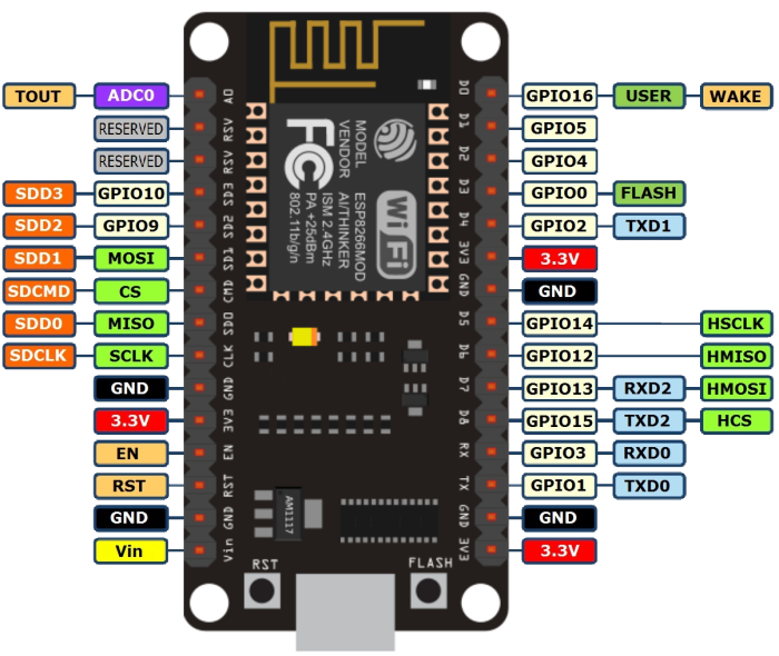
## Pinout
Remember the numbers to use are the ones after _GPIO_ (ej pin 2 is _GPIO2_) you can also use the _defined_ name of the pin (ej defined name D4 is _GPIO2_):
* **D4** = GPIO_2 = **2**
* **D5** = GPIO_14 = **14**, etc...
## Using Arduino IDE
Install ESP8266 board in arduino IDE adding this address on _Aditional Board manager URL's_ window on the _preferences_ menu item:
`http://arduino.esp8266.com/stable/package_esp8266com_index.json`

Install **ESP8266 board** in Arduino _Board Manager_:

You should now see the ESP8266 board in your Arduino Boards menu.
Select **NODE MCU** on the `Tools / Ports` menu.

## Installing the Drivers
:::warning
:warning: We found some computers (OSX and some windows versions) need an extra step for the board to be recognize.
:::
Go to the page below and look for the Driver that matches your operative system.
https://www.silabs.com/products/development-tools/software/usb-to-uart-bridge-vcp-drivers
If you have one of the bigger boards that says _LoLin_ on the back use this driver instead:
https://sparks.gogo.co.nz/ch340.html
Download and install them as any other software. Sometimes is necessesary rebooting the machine
Now you should another port on your `Tools / Ports` menu.

## Test the board
1. Load the `Files -> Examples -> ESP8266 -> Blink` example
2. For faster uploads you can select the maximum speed on the _tools -> Upload Speed_ menu.
3. Select the right USB port on the _tools -> port_ menu.
4. Click the **UPLOAD** button and wait for the process to finish.

If everything works fine your ESP8266 should be blinkig!
## Input/Output
Digital input/output can be used on all GPIO.
### DigitalWrite
```clike
void setup() {
pinMode(BUILTIN_LED, OUTPUT); // Initialize the BUILTIN_LED pin as an output
}
// the loop function runs over and over again forever
void loop() {
digitalWrite(BUILTIN_LED, LOW); // Turn the LED on (Note that LOW is the voltage level
// but actually the LED is on; this is because
// it is acive low on the ESP-01)
delay(1000); // Wait for a second
digitalWrite(BUILTIN_LED, HIGH); // Turn the LED off by making the voltage HIGH
delay(2000); // Wait for two seconds (to demonstrate the active low LED)
}
```
### DigitalRead
```clike
// You can try a digital input with a push button connected to pin D4 (GPIO 2)
int pushButton = D4;
// the setup routine runs once when you press reset:
void setup() {
// initialize serial communication at 9600 bits per second:
Serial.begin(9600);
// make the pushbutton's pin an input and activate the internal pullup resistor:
pinMode(pushButton, INPUT_PULLUP);
}
// the loop routine runs over and over again forever:
void loop() {
// read the input pin:
int buttonState = digitalRead(pushButton);
// print out the state of the button:
Serial.println(buttonState);
delay(1); // delay in between reads for stability
}
```
### AnalogRead
Esp8266 **only has one analog** channel that can be used on pin A0.
```clike
// the setup routine runs once when you press reset:
void setup() {
// initialize serial communication at 9600 bits per second:
Serial.begin(9600);
}
// the loop routine runs over and over again forever:
void loop() {
// read the input on analog pin 0:
int sensorValue = analogRead(A0);
// print out the value you read:
Serial.println(sensorValue);
delay(1); // delay in between reads for stability
}
```
### AnalogWrite
PWM has a resolution of 10 bits (1024 values) at 1kHz and can be used on pins D2, D5, D6 and D8:
```clike
int led = D4; // the PWM pin the LED is attached to
int brightness = 0; // how bright the LED is
int fadeAmount = 5; // how many points to fade the LED by
// the setup routine runs once when you press reset:
void setup() {
// declare pin to be an output:
pinMode(led, OUTPUT);
}
// the loop routine runs over and over again forever:
void loop() {
// set the brightness:
analogWrite(led, brightness);
// change the brightness for next time through the loop:
brightness = brightness + fadeAmount;
// reverse the direction of the fading at the ends of the fade:
if (brightness <= 0 || brightness >= 255) {
fadeAmount = -fadeAmount;
}
// wait for 30 milliseconds to see the dimming effect
delay(30);
}
```
## WiFi
File -> Examples -> ESP8266WiFi -> WiFiClient
```clike
#include <ESP8266WiFi.h>
const char* ssid = "your-ssid";
const char* password = "your-password";
void setup() {
Serial.begin(115200);
delay(10);
Serial.println();
Serial.print("Connecting to ");
Serial.println(ssid);
WiFi.begin(ssid, password);
while (WiFi.status() != WL_CONNECTED) {
delay(500);
Serial.print(".");
}
Serial.println("");
Serial.println("WiFi connected");
Serial.println("IP address: ");
Serial.println(WiFi.localIP());
}
void loop() {
}
```
> This is mostly similar to WiFi shield library. Differences include:
>WiFi.mode(m): set mode to WIFI_AP, WIFI_STA, WIFI_AP_STA or WIFI_OFF.
call WiFi.softAP(ssid) to set up an open network
call WiFi.softAP(ssid, password) to set up a WPA2-PSK network (password should be at least 8 characters)
WiFi.macAddress(mac) is for STA, WiFi.softAPmacAddress(mac) is for AP.
WiFi.localIP() is for STA, WiFi.softAPIP() is for AP.
>WiFi.printDiag(Serial) will print out some diagnostic info
WiFiUDP class supports sending and receiving multicast packets on STA interface. When sending a multicast packet, replace udp.beginPacket(addr, port) with udp.beginPacketMulticast(addr, port, WiFi.localIP()). When listening to multicast packets, replace udp.begin(port) with udp.beginMulticast(WiFi.localIP(), multicast_ip_addr, port). You can use udp.destinationIP() to tell whether the packet received was sent to the multicast or unicast address.
> WiFiServer, WiFiClient, and WiFiUDP behave mostly the same way as with WiFi shield library. Four samples are provided for this library. You can see more commands here: http://www.arduino.cc/en/Reference/WiFi
>
## Installing a library
To open the Arduino library manager go to:
Sketch -> Include Library -> Manage libraries.

There you can search and install all kind of libraries.
___
:::info
**Useful references**
[ESP8266 Arduino Core reference](http://esp8266.github.io/Arduino/versions/2.0.0-rc2/doc/reference.html)
:::
## Continue...
Learn now about MQTT and how to make your NODE MCU talk to other boards over the internet
:arrow_forward: [**Read MQTT with Arduino**](https://hackmd.io/@8sCwEDXZRLu279SP363xRQ/SyTkT6qWO)
 Sign in with Wallet
Connect another wallet
Sign in with Wallet
Connect another wallet