# SWARMING LED SCARVES
- this notepad: https://hackmd.io/@100ideas/scarfswarm ([edit](https://hackmd.io/@100ideas/scarfswarm/edit))
- repo (temporary): https://github.com/counterbeing/bikelights
- LED-swarm fork https://github.com/100ideas/LED-swarm
- this project is an adaption of [Chuck Sommerville's **led-swarm** project](https://github.com/chucks13/LED-swarm/blob/master/theory.txt) - ~20 independant 150-LED staffs that synchronize animations over 2.4ghz, built with:
- [TeensyLC microcontroller](https://www.pjrc.com/store/teensylc.html)
- [nRF24L01+ 2.4 Ghz radio](http://a.co/d/3rhLgCT)
- [WS2811](https://hackmd.io/@100ideas/scarfswarm#LED-strips) LED strips
- [FastLED.h library](https://github.com/FastLED/FastLED)
- [NRFLite.h library](https://github.com/dparson55/NRFLite)
- chuck's repo: https://github.com/chucks13/LED-swarm/blob/master/theory.txt
- fb [Chuck Sommerville thread on LEDs ARE AWESOME](https://www.facebook.com/groups/LEDSAREAWESOME/1046179785577480/?comment_id=1046277275567731&reply_comment_id=1066784526850339)
- fb comments for strobe-sync led-swarm fork: https://www.facebook.com/groups/LEDSAREAWESOME/permalink/1072783566250435/
## Final Push
### PCBs Needed
- 10 scarves
- 5 for big red
- 6 extra
### Inventor Needed
- 21 PCB boards
- 21 Arduinos
- 21 NRF
- Capacitors
- 15 Rotary Encoders
## Description
Our project adapts Chuck's work for two non-staff form-factors, faux-fur led-strip scarfs and [adafruit flora sewable RGB neopixel](https://www.adafruit.com/product/1559)-encrusted sequin capes. A rotary/push-button encoder provides the user interface to each unit. The encoder can be used to select/control animations (in solo mode or master mode) and various swarm features - leave swarm (for 10 min), become "Master of the Swarm", and trigger fast synchronized swarm strobing based on encoder clicks (everyone).
Chuck's led-swarm library is designed to synchronize the display of deterministic animations with frame-level accuracy across the entire swarm. We aren't sure if we need this level of synchronization (but I bet it looks cooler!).
Our animations are designed to be parameterized with the rotary encoder (colors & speed usually) and will be displayed on various lengths of led strand, so instead of trying to synchronize all members to show animations that are exactly in sync, we just want each member to play the same animation pattern, perhaps out of sync due to strip lengths, but synchronized in real-time with the parameters of the Master node. Also synchronized stobes triggered by any member for the bass drops that deserve it.]
### video explainers
[
Scarfswarm / bikeslights ws2811 strip components & design tour (youtube 8m)](https://youtu.be/d4aWEN4XvKw)
[
scarfswarm sequin shawl neopixel gemma diy led strip glowy demonstration (youtube 8m)](https://youtu.be/DPaRKGL4-40)
[
Scarfswarm / bikelights Big Red animation demo (youtube 2m)](https://youtu.be/5sAtdrZpyJc)
### Components for 10 units
- SK9822 led strip in IP66 tubing, 24 meters (need ~2.4 meters per scarf / 75 leds)
- [30leds/m](https://www.aliexpress.com/store/product/5M-DC5V-30leds-m-SK9822-addressable-led-pixel-strip-IP66-waterproof-in-silico-tube-WHITE-PCB/701799_32883251315.html) ($5.60/meter), or
- [60leds/m](https://www.aliexpress.com/store/product/4M-DC5V-SK9822-addressable-led-pixel-strip-60leds-m-with-60pixels-m-BLACK-PCB-waterproof-in/701799_32885436235.html) ($8.50/meter)
- *I like the sk9822 even though it is a few bucks more expensive b/c it supposedly has some hardware bug fixes related to timing and voltage regulation*
- [TeencyLC w/ header pins](https://www.pjrc.com/store/teensylc_pins.html) ($14.65/1), 10x
- *we ended up using arduino nanos but basically ran out of program memory before implementing all the desired features. Don't be dumb like us; spend a bit more for a board like the teensy that has large program memory, your leds will be more awesome*
- Bourns PEC11 12mm 24-pulse rotary encoder (PEC11-4215F-S24) [adafruit #377](https://www.adafruit.com/product/377) ($4.50/1); [datasheet](https://cdn-shop.adafruit.com/datasheets/pec11.pdf) (need 10x)
- [usb type a male adapter 20-pack]( https://www.amazon.com/gp/product/B07GGJGB7Q) ($11)
- [PowerAdd Slim 2 5000 mAh Compact Battery Packs](https://www.amazon.com/dp/B00KG45W08) ($13)
- [JST 4pin male-female connector pigtails, pack of 20](https://www.amazon.com/gp/product/B075K3M1TB) ($11)
- [112Pcs 2.54mm Male and Female Pin Header Connector Assortment Kit, 100pcs Stackable Shield Header](https://www.amazon.com/gp/product/B07CWSXY7P) ($13)
- [Capri Tools 20011 Automatic Wire Stripper and Cutter
](https://www.amazon.com/gp/product/B01018CX46) ($14)
- [silicone stranded wire, 20 gauge, 100ft, 2-color pack](https://www.amazon.com/gp/product/B01F8PO6VK) ($19)
- [silicone stranded wire, 26 gauge, 26ft, 5 color pack](https://www.amazon.com/gp/product/B07G7W7G4T) ($14)
- [silicone stranded wire, 26 gauge, 32ft, 5 color pack](https://www.amazon.com/gp/product/B07G872J7T) ($14)
#### components for sequin shawl
- 60-90 individual [adafruit flora sewable RGB neopixels](https://www.adafruit.com/product/1559) ($34.95/20) or [amazon](https://www.amazon.com/gp/product/B00SK8OWHQ) ($32.28/20)
- [2-ply or 3-ply conductive **stainless steel** conductive thread](https://www.amazon.com/gp/product/B00SK8M62Y) ($6.25/60ft) (don't get silver, it will tarnish and then fail)
- [awesome sequined cape](https://www.amazon.com/gp/product/B01GCCF2F2) ($14.90/1)
- [USB 2.0 Type A Male Adapter w/ cover](https://www.amazon.com/gp/product/B07C6S135J) ($10.99/20)
#### unused but potentially useful
- [Arduino nano w/ integrated nRF24l01 board, 2x, $14](https://www.amazon.com/gp/product/B07N2P8FCD/)
- 74HCT245 8-channel buffer chip / 3.3v<->5v logic level shifter (used in OctoWS2811): [amazon](https://www.amazon.com/dp/B00CHTJJX6) ($13.59/10)
- note: I wanted to find a smaller solution since I don't need 8 channels, but after skimming the EE blogs I noticed many of them consistently ranked this chip as the best, and I couldn't find any cheaper options on amazon...
- [datasheet](https://assets.nexperia.com/documents/data-sheet/74HC_HCT245.pdf); [adafruit guide to level shifting](https://learn.adafruit.com/neopixel-levelshifter/shifting-levels) w/ this chip
### Libraries
- https://github.com/brianlow/Rotary
- FastLED
- NRFLite
## JST connectors/wires + other components
### YES
- 4x2 2.54mm dupont female/female connector wire assembly https://www.amazon.com/Pc-Accessories-Connectors-Sockets-6P-20cm-4PK/dp/B07DFBPZLJ
- Tantalum capacitor kit https://www.amazon.com/gp/product/B0734TWB8Y/
### Maybe
- 2x4P Jumper Wires Double Row Head Ribbon Cables Pi Pic Breadboard 31cm Long (china) https://www.newegg.com/p/0HZ-004B-003U7
- 4-pin male + female JST connectors + wire: https://www.amazon.com/gp/product/B01E902D0G
- ST SM 5 Pin Connector wire assembly https://www.amazon.com/ACTOO-Connector-Power-Female-Adapter/dp/B07GGJGB7Q/
- JST on digikey https://www.digikey.com/en/supplier-centers/j/jst
- molex on digikey https://www.digikey.com/en/supplier-centers/m/molex
- https://www.digikey.com/product-detail/en/samtec-inc/IDSD-04-D-10.00/SAM8816-ND/2685119

## Next Steps
### 31 Jul 2019
- cory orders PCBs from OSHpark
- mac orders JST + Cables
### 18 Jun 2019
- Decide on 30leds/m or 60leds/m SK9822 LED strips
- estimating SK9822 led module draws 0.040mA
- consider 2-meter length, 60 vs 120 leds
- 60 draws ~2.4 amps, 120 draws ~4.8 amps (full rgb on all leds max power on is 60 mA / led)
- at 5v thats 12 watts or 24 watts
- our jackery pocket usb battery packs are rated for 6000 mAh or 12000 mAh with max current of 2.1 amps
- note that mAh rating of these batteries is *sneakily* based on nominal lithium battery voltage of ~3.7v, so 6000 mAh really translates to 4440 or 8880 mAh hours at 5v (2-3 or 3-5 hr runtime for our leds when pulling constant 2 amps)
- so it may not be wise to try to use more than 60-80 leds per battery... but it would probably work most of time
- Get [RF modules](https://www.amazon.com/gp/product/B072BLN8SZ) (cory wants this vendor for the included 3v-5v breakout boards) ($9.50/4)
- chuck used [nRF24L01+ 2.4 Ghz radio](http://a.co/d/3rhLgCT) ($11.98/10)
- Make and document circuit that can relay animations between two scarfs
- Add additional logic for things like
- Blinking when in proximity (indicate if you are a slave, master can be implied?)
- Settings menu of some kind
- LOL this is gonna be a fair amount of work we need more bullet points...
- try to implement Chuck's requested improvements in Eagle to his *Swarm Rev II (Swarm3.zip)* board - see notes below
- Determine if TeensyLC (which is 3v logic) needs buffer chip like `4HCT245` used in OctoWS2811 to convert 3.3v logic levels to 5v levels for SK9822 strand
- some EE blogs say 3.3v logic into 5v logic will sometimes work
- but if problems, use a level shifter!
### In Progress
- Determine if WS* can work, or if we need a four strand cable.
- default to SK9822 via Ray unless we can get expert advice confirming Teensy + nRF with fast data rate (not 1 packet per 2 sec) will not cause problems per FastLED interrupt wiki note.
### Done
- Determine if we can use existing PCB boards, or print new ones
- no, we fabbed led-swarm v1 (AKA "Swarm I") which was for nano, now we are using teensy so we need v3 AKA "Swarm II"
- (mac) get additional components
- TeensyLC from amzn
- larger order from pjrc
- 4HCT245 buffer chip
---
## Q/A with Chuck Sommerville
https://www.facebook.com/groups/LEDSAREAWESOME/permalink/1046179785577480/?comment_id=1070931573102301
**Mac:**
> Hi Chuck, I was wondering if you are using a teensy or an arduino nano in your project? Looking at the source (https://github.com/chucks13/LED-swarm/blob/master/led_swarm_3.ino#L31) I see configuration variables for a variety board/led-chip combinations, and currently TEENSY150 set of variables is used, which specifies Teensy + WS2812 + 150 LEDs.
>
> I read on the FastLED wiki that its driver for 3-wire strips like ws281x can cause delays when reading serial data / using i2c / reading interrupts - does this cause an issue with the nRF radio polling/control code on arduino nano? Did you switch to Teensy to avoid it? Thanks! (https://github.com/FastLED/FastLED/wiki/Interrupt-problems)
**Chuck:**
> The source supports either, and I have had it work on both, but the size of the project is quickly getting too large for the Nano. I would discourage using the Nano if you want your device to properly sync with other devices. My hope making it open source is that additional visual effects will be contributed by other artists. I will do my best to curate the project. That said, the communication rate is extremely low band with with only a 32 byte packet being send every 2 seconds.
>
> Also, the Swarm II board is built for the Teensy LC. All of the 20 I am taking to BM are Teensy. I consider the Nano to be prototype only. If you study the current code, you might notice a define fir STRONGMAN. This is a controller only transmitter that will show data on the wands for an event we are planning at BM, and since as a controller, it does not have to display any effects, It comments out much of the code so it can read a sensor and transmit display data (effect #200)
**Mac:**
> Ok great, I am leaning towards Teensy LC too (is it the same pinout as nano? we can figure it out)
>
> Re contributions, we are implementing control scheme based on a pushbutton rotary encoder (https://github.com/brianlow/Rotary) that will have two modes, one for controlling animation parameters and another for controlling joining/becoming master/ignoring the swarm. We were also hoping to implement a strobe-broadcast mode which would cause the swarm to mix a strobe-like pulse into the current animation when triggered by any user. It would be awesome if we could trigger multiple strobes per second but I see that I need to better understand the data rate constraints.
>
> For our application we were planning to synchronize the swarm animations to a lesser extant than your system: we just want nodes to use the same animation pattern + 1 or 2 parameters such as color or speed, not worrying about synchronizing to exact frame. This is because some of our nodes will have led strips of varying lengths.
**Chuck:**
> Pinouts are different. Some of those are defined in the code. Also the modules have pins in very different positions. The Swarm II board is for Teensy LC, I dont remember if the Swarm I board is checked into the project or not. I still have some from the first board run, but I only use them for special projects like the Strongman controller.
> ...
> Look int0 the swarm folder now. There is a file called [swarm3.zip](https://github.com/chucks13/LED-swarm/blob/master/swarm/Swarm3.zip), which I have been calling the **Swarm II board**. **If you are talented in eagle. I ask you to correct the wiring of the radio pins, and find a way to add a vcut so the board can be easily broken apart**.
>
> Also, **the radio should be shifted a pin to the right, so it is right justified with the Teensy board**. That will make the radio crystal clear the printed tube assembly bettter.
>
> **Another improvement would be holes for an optional capacitor like the one suggest in many of the NFR24L01 projects.**
---
## Concerns
### [FastLED: input problems w/ WS281x leds when other libraries/components need moderate data throughput](https://github.com/FastLED/FastLED/wiki/Interrupt-problems):
**UPDATE based on feedback from Chuck, we should use a TeensyLC**
> If you are using a 3-wire led chipset, (aka Neopixels, WS2812, TM1809), you may have run into some problems when trying to pair it with reading serial data, wifi (for example, on an esp8266), or using i2c, or other libraries.
>
> The problem is, in a nutshell, interrupts.
>
> Writing out WS2812 data requires some pretty tight timing. Tight enough that FastLED disables interrupts while it is writing out led data. This means that while the led data is being written out, any interrupts that happen will be delayed until all the led data is written out. How long will that be for? Depends on the number of leds. WS2812 led data takes 30µs per pixel. If you have 100 pixels, then that means interrupts will be disabled for 3000µs, or 3ms.
---
# NRF24L01+ notes
## Hello World - 2.4ghz scanner
NRFLite lib includes a rough 2.4 Ghz signal scanner with serial ascii spectrogram output - good way to start playing around w/ nRF chip
- https://github.com/dparson55/NRFLite/blob/master/examples/ChannelScanner/ChannelScanner.ino
- (old) alternate source code http://arduinoinfo.mywikis.net/wiki/Nrf24L01-Poor_Man%27s_2
## Learning
- nordic semi [nRF24L01+ Datasheet](https://infocenter.nordicsemi.com/pdf/nRF24L01P_PS_v1.0.pdf)
Tutorials
- https://www.deviceplus.com/how-tos/arduino-guide/nrf24l01-rf-module-tutorial/
Getting Started with nRF24L01+ on Arduino (2011)
- https://maniacbug.wordpress.com/2011/11/02/getting-started-rf24/
- http://arduinoinfo.mywikis.net/wiki/Nrf24L01-2.4GHz-HowTo
- https://www.youtube.com/watch?v=wlhuO82IZjQ
More poor Man's 2.4 GHz Scanner links (going back in time)
- http://arduinoinfo.mywikis.net/wiki/Nrf24L01-Poor_Man%27s_2
- https://forum.arduino.cc/index.php?topic=54795.msg392325#msg392325
- https://weatherhelge.wordpress.com/2014/12/31/2-4ghz-scanner-using-rftoy/
- https://www.riyas.org/2014/06/a-simple-24ghz-spectrum-analyser-arduino-lcd-shield.html
SPI on arduino
- https://www.deviceplus.com/how-tos/arduino-guide/arduino-communication-protocols-tutorial/
## Range
https://github.com/maniacbug/RF24:
> Here are some results from measurements I have taken, using the basic $4 iTeadStudio units. I recommend that everyone take their own measurements in their particular circumstances.
>
> - non-plus unit, 2MBps (worst case), 41+ ft line of sight indoors, immediate dropoff with any deviation from LOS. (41 ft is as far as I can go in my house without turning a corner)
> - Plus unit, 250kbps (best case), 46 ft around two corners indoors, 49 ft around one corner. More importantly, at 250k, packet loss is almost negligible through almost all of that range.
> - Both units at 1MBps, plus unit gets about 10% range improvement over non-plus in almost all situations.
http://arduinoinfo.mywikis.net/wiki/Nrf24L01-Info:
> Thankfully for us, the guys at Nordic made the IO pins 5V-tolerant, which means you can run your microcontroller at 5V and it won’t fry this chip.Remember, though, that you can’t run the 24L01 at 5V – the data sheet gives an operating range of 1.9 to 3.6V for Vcc (the chip will be run at 3.3V in most circumstances). The SPI interface uses four pins, CSN, SCK, MISO, and MOSI for data transmission and reception.The CSN (chip select not) pin is active-low, and is normally kept high.When this pin goes low, the 24L01 begins listening on its SPI port for data and processes it accordingly.The remaining three pins should be tied to the user’s hardware SPI interface, to the same pins as their name suggests (SCK to SCK, MISO to MISO, and MOSI to MOSI). The remaining two pins are CE and IRQ.CE is used to control data transmission and reception when in TX and RX modes, respectively.IRQ is the interrupt pin, and is active-low.There are three internal interrupts that can cause this pin to go low when they are active.Each of these bits can be masked out such that when the bit’s respective interrupt becomes active, the status of the IRQ pin is not changed.
## Pinout


---
## Teensy Notes
FastLED teensy SPI
https://www.pjrc.com/teensy/td_libs_FastSPI_LED.html
need higher clock speed for longer strips for refresh rate, but lower frequency for longer conductor lengths
- https://forum.pjrc.com/threads/55459-APA102-SK9822-LED-Strips-in-Parallel
Get four hardware SPI lines on Teensy
https://github.com/FastLED/FastLED/wiki/SPI-Hardware-or-Bit-banging#getting-four-hardware-spi-lines-for-the-apa102-out-of-the-teensy-303132
FastLED Teensy note (we want ARM):
- "Teensy 2, Teensy++ 2, Teensy 3.0, Teensy 3.1/3.2, Teensy LC - arduino compataible from pjrc.com with some extra goodies (note the teensy 3, 3.1, and LC are ARM, not AVR!)"
- "Despite their small size, the Teensy 3 series dev boards pack a lot of horsepower as they use ARM Cortex M4 CPUs with plenty of RAM. The Teensy 3.2 runs at 72MHz and has 64kB RAM, while the Teensy 3.6 runs at 180 MHz, and has 256kB RAM. Even better, the processors in the Teensy 3 boards come with a DMA engine that can move data from memory to pins to allow refreshing the display in the background, so the main program can run without as many interruptions.
- https://learn.adafruit.com/smartmatrix-animated-gif-player
4320 LEDs driven by Teensy 3.1 + Octo
- https://community.arm.com/developer/ip-products/system/b/embedded-blog/posts/led-video-panel-at-maker-faire-2014-concept-and-development
- they used 6 200W ATX style 40 amp 5v PSU, 1200W total
- if they had used 1560 leds instead, it would scale to 1560 / 4320 * 1200 W = 433 Watts
- to drive 1560 pixels simplex (one channel) would take 1560 * 30us + 50 us = 46.8 ms ~= 21.37 Hz
---
# LED strips
## 2019-06-21 mac's order from Ray Wu
- **5 units $21/unit**: 30leds/m; 5m **WS2815** DC12V addressable full color RGB 5050 LED strip;waterproof in silicon tube; WHITE PCB
- https://www.aliexpress.com/item/32921411443.html
- **4 units $28/unit**: 5M DC5V 30leds/m **SK9822** addressable led pixel strip;IP66;waterproof in silico tube; WHITE PCB; 30pixels/m
- https://www.aliexpress.com/item/32883251315.html
- shipping DHL 2019.06.28 $34.79
- ordered 2019-06-21, arrived 2019.06.28
## Ray Wu's LED STORE
([SK9822](https://cpldcpu.wordpress.com/2016/12/13/sk9822-a-clone-of-the-apa102/) is a clone of APA102 "dotstar-style" 4-wire individually adddressable LED strand that allegedly fixes [some clock/logic flaws that show up in longer lengths of APA102](https://www.pjrc.com/why-apa102-leds-have-trouble-at-24-mhz/))
- [collection of SK9822 Led strands](https://www.aliexpress.com/store/group/SK9822-addressable-strip/701799_507751111.html)
- [4M DC5V SK9822 addressable led pixel strip;60leds/m with 60pixels/m;BLACK PCB;waterproof in silicon tube](https://www.aliexpress.com/store/product/4M-DC5V-SK9822-addressable-led-pixel-strip-60leds-m-with-60pixels-m-BLACK-PCB-waterproof-in/701799_32885436235.html) ($8.50/meter; 4 meter length)
- [5M DC5V 30leds/m SK9822 addressable led pixel strip;IP66;waterproof in silico tube;WHITE PCB;30pixels/m](https://www.aliexpress.com/store/product/5M-DC5V-30leds-m-SK9822-addressable-led-pixel-strip-IP66-waterproof-in-silico-tube-WHITE-PCB/701799_32883251315.html) ($5.60/meter; 5 meter length)
## APA102 / SK9822
Ray: https://www.aliexpress.com/item/32883251315.html?storeId=701799
documentation:
- [sk9822: a clone of the apa102 (technical review w/ scope)](https://cpldcpu.wordpress.com/2016/12/13/sk9822-a-clone-of-the-apa102/)
- [apa102 has trouble at 24 mhz, what about sk9822](https://www.pjrc.com/why-apa102-leds-have-trouble-at-24-mhz/)
- https://cpldcpu.com/2014/08/27/apa102/
- https://cpldcpu.com/2014/11/30/understanding-the-apa102-superled/
## WS281x
(WS2811/WS2812/WS2813/WS2813B)
- [Teensy 3.0 48Mhz/76Mhz problems w/ WS2812B leds](https://github.com/FastLED/FastLED/issues/78) (FastLED github)
- solution was to use `75HCT245` level converter w/ fresh teensy
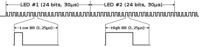
### WS2811 data format & timing notes
> The WS2811 controller chips in each LED require a special 1-wire data format with precise timing. Data is always transmitted at 800 kbits/sec, where the width of each pulse indicates if it's a 0 or 1.
>
> 
>
> Each LED consumes the first 24 bits it receives, then begins passing all remaining data to the following LED. The first 24 pulse control the first LED, then the next 24 control the 2nd LED, and so on. A silent time of 50 us or greater marks the beginning of a new data frame. (this means last pulse of current "frame" i.e. past last LED should be 50 us wide)
>
> [OctoWS2811](https://www.pjrc.com/store/octo28_adaptor.html) is named "Octo" because it transmits 8 streams of these pulses simultaneously. Because each LED requires 30 microseconds, eight parallel outputs allows a very large LED array to update 8 times faster. In this 4320 LED project, each of the 8 outputs controls 540 LEDs, which requires 16.2 ms, or approximately half of a 30 Hz video frame time.
>
> \- [arm.com: "LED Video Panel at Maker Faire 2014: Concept and Development"](https://community.arm.com/developer/ip-products/system/b/embedded-blog/posts/led-video-panel-at-maker-faire-2014-concept-and-development)
### WS2812 vs WS2812B vs WS2813
> The image is mainly about the difference between the work principle of WS2812 and WS2813 LED strip. The most obvious difference is: when the led one of the WS2812 was broken, it will affect the other led working, but the WS2813 will not appear above situation.
>
> The features and benefits between WS2812 and WS2812B is the WS2812B has intelligent reverse connect protection and the power supply reverse connection does not damage the IC.
>
> Nowadays it comes to the latest version of the WS2812, which is **WS2813**.
>
> WS2812 only one data signal when one led broken may affect the other led working, which only die is package in 5050 RGB LED Chip. But WS2813 led have 2 data signal, any pixel’s failure won’t affect signal transfer and its total emitting effect, unless two consecutive adjacent LED are Broken. WS2813 adopted the upgraded chips led so WS2813 led make digital led project is more reliable than before.
>
> \- [elecrow.com: what’s the difference? WS2812 VS WS2813](https://www.elecrow.com/blog/ws2813-vs-ws2812/)
## level shifting for 3.3v logic (teensy) for long/fast LED strips
- https://learn.adafruit.com/neopixel-levelshifter/shifting-levels
- http://www.electrobob.com/ws2812-level-translator/
in general, buffer chip to go 3.3 -> 5 may not be needed, esp if strip is supplied a Vin on the low side of 5V... many anecdotal reports of directly driving strips from 3.3v output from teensies.
### Do You Even Need A Level Shifter? (hackaday)
> If the 3.3V part is an output and the 5V one an input, the lower voltage part can hardly damage the higher voltage one with overvoltage. And you are not likely to encounter a logic input that might demand so much current that it would damage your output (If you do, use a buffer!). If you are lucky the logic voltage ranges of the two devices may even coincide. For example 3.3V TTL logic shares the 0.8V and 2V thresholds for logic 0 and logic 1 transitions with 5V TTL logic, so a 3.3V TTL output can drive a 5V TTL input without any extra hardware required.
> \- https://hackaday.com/2016/12/05/taking-it-to-another-level-making-3-3v-and-5v-logic-communicate-with-level-shifters/
### CHEATING AT 5V WS2812 CONTROL TO USE 3.3V DATA (hackaday)
> 
> If you’re looking to control WS2812 (or Neopixel) LEDs using a microcontroller running at 3.3 volts, you might run into some issues. The datasheet tells us that a logic high input will be detected at a minimum voltage of 0.7 * Vcc. If you’re running the LED at 5V, this means 5 V * 0.7 = 3.5 V will be needed for the WS2812 to detect a ‘1’ on the data line. While you might get away with using 3.3 V, after all the specification in the data sheet is meant to be a worst case, it’s possible that you’ll run into reliability issues.
>
> See hackaday post on [building level shifters](http://hackaday.com/2016/12/05/taking-it-to-another-level-making-3-3v-and-5v-logic-communicate-with-level-shifters/) or consider this hack:
>
> For the Big Button project at CrashSpace, [todbot] used an ESP8266 running at 3.3 volts and WS2812 LEDs running at 5 V. To perform the level shift, a signal diode is placed in series with the power supply of the first LED. This drops the first LED to 4.3 V, which means a 4.3 V * 0.7 = 3.01 V signal can be used to control it. The logic out of this LED will be at 4.3 V, which is enough to power the rest of the LEDs running at 5 V.
>
> This little hack means a single diode is all that’s needed to control 5 V LEDs with a 3.3 V microcontroller.
> \- https://hackaday.com/2017/01/20/cheating-at-5v-ws2812-control-to-use-a-3-3v-data-line/
### Testing level shifters for running Adafruit NeoPixel strips from a 3.3 Volt Teensy
> If you’re running NeoPixel LED strips off a Teensy 3, maybe because you want to put 180 LEDs on a hat, then you need a level shifter. But which one? The NeoPixel data protocol is high speed and pretty harsh on timing requirements and I’ve had a bugger of a time getting reliable data from the Teensy to these strips. Hence I’ve tested a bunch of shifters. I tried a TXS-0102, TXB-0108, 74HCT245, PCA9306, and a MOSFET based shifter.
>
> The Teensy outputs data at 3.3 Volt, the strips expect 5 Volts. Or rather, the strips might see 3.3 Volts as a digital 1 or they might not. If you want some reliability, then you’re better off shifting the Voltage level up to 5.
>
> Each LED reads the data it needs and passes on the rest, regenerating the signal to nice square pulses, so there is no decline in signal quality along the strip. Well, that’s the theory. In reality, all sorts of weird failure modes can happen.
>
> Anyway, short conclusion from this testing is: use a TXS-0102 shifter if you’re tight on space and running one or two strips, use a 74HCT245 if you’re not or you are running three to eight strips. **The 74HCT245 was the only shifter to give perfect performance**, everything else had some kind of problem.
> \- http://happyinmotion.com/?p=1247
---